How to develop SIF proof tests

Proof testing is an integral part of the maintenance of the safety integrity of our safety instrumented systems (SIS) and safety-related systems (e.g. critical alarms, fire & gas systems, instrumented interlock systems, etc.). A proof test is a periodic test to detect dangerous failures, test safety-related functionality (e.g. reset, bypasses, alarms, diagnostics, manual shutdown, etc.), and ensure the system meets company and external standards. The results of proof testing are also a measure of the effectiveness of the SIS mechanical integrity program and the field reliability of the system.
Proof test procedures cover test steps from acquiring permits, making notifications and taking the system out of service for testing to ensuring comprehensive testing, documenting the proof test and its results, placing the system back in service, and evaluating the current test results and previous proof test results.
ANSI/ISA/IEC 61511-1, Clause 16, covers SIS proof testing. ISA technical report TR84.00.03 – “Mechanical Integrity of Safety Instrumented Systems (SIS),” covers proof testing and is currently under revision with a new version expected out soon. ISA technical report TR96.05.02 – “In-situ Proof Testing of Automated Valves” is currently under development.
UK HSE report CRR 428/2002 – “Principles for proof testing of safety instrumented systems in the chemical industry” provides information on proof testing and what companies are doing in the UK.
Develop the procedures
A proof test procedure is based on an analysis of the known dangerous failure modes for each of the components in the safety instrumented function (SIF) trip path, the SIF functionality as a system, and how (and if) to test for the dangerous failure mode. Procedure development should start in the SIF design phase with the system design, selection of components, and determination of when and how to proof test. SIS instruments have varying degrees of proof testing difficulty that must be considered in the SIF design, operation and maintenance. For example, orifice meters and pressure transmitters are easier to test than Coriolis mass flowmeters, mag meters or through-the-air radar level sensors. The application and valve design also can affect the comprehensiveness of the valve proof test to ensure that dangerous and incipient failures due to degradation, plugging or time-dependent failures don’t lead to a critical failure within the selected test interval.
While proof test procedures are typically developed during the SIF engineering phase, they should also be reviewed by the site SIS Technical Authority, Operations and the instrument technicians who will be doing the testing. A job safety analysis (JSA) should also be done. It’s important to get the plant’s buy-in on what tests will be done and when, and their physical and safety feasibility. For example, it does no good to specify partial-stroke testing when the Operations group will not agree to do it. It’s also recommended that the proof test procedures be reviewed by an independent subject matter expert (SME). The typical testing required for a full function proof test is illustrated in Figure 1.
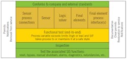
Figure 1: A full function proof test specification for a safety instrumented function (SIF) and its safety instrumented system (SIS) should spell out or refer to the steps in sequence from test preparations and test procedures to notifications and documentation.
Proof testing is a planned maintenance action that should be performed by competent personnel trained in SIS testing, the proof procedure, and the SIS loops they’ll be testing. There should be a walk-through of the procedure prior to performing the initial proof test, and feedback to the site SIS Technical Authority afterward for improvements or corrections.
Failure modes
There are two primary failure modes (safe or dangerous), which are subdivided into four modes—dangerous undetected, dangerous detected (by diagnostics), safe undetected and safe detected. Dangerous and dangerous undetected failure terms are used interchangeably in this article.
In SIF proof testing, we are primarily interested in dangerous undetected failure modes, but if there are user diagnostics that detect dangerous failures, these diagnostics should be proof tested. Note that unlike user diagnostics, device internal diagnostics typically can’t be validated as functional by the user, and this can influence the proof test philosophy. When credit for diagnostics are taken in the SIL calculations, the diagnostic alarms (e.g. out-of-range alarms) should be tested as part of the proof test.
Failure modes can be further divided into those tested for during a proof test, those not tested for, and incipient failures or time-dependent failures. Some dangerous failure modes may not be directly tested for various reasons (e.g. difficulty, engineering or operational decision, ignorance, incompetence, omission or commission systematic errors, low probability of occurrence, etc.). If there are known failure modes that will not be tested for, compensation should be done in device design, test procedure, periodic device replacement or rebuild, and/or inferential testing should be done to minimize the effect on SIF integrity of not testing.
An incipient failure is a degrading state or condition such that a critical, dangerous failure can reasonably be expected to occur if corrective actions are not taken in a timely manner. They are typically detected by performance comparison to recent or initial benchmark proof tests (e.g. valve signatures or valve response times) or by inspection (e.g. a plugged process port). Incipient failures are commonly time-dependent—the longer the device or assembly is in service, the more degraded it becomes; conditions that facilitate a random failure become more likely, process port plugging or sensor buildup over time, the useful life has run out, etc. Therefore, the longer the proof test interval, the more likely an incipient or time-dependent failure. Any protections against incipient failures also must be proof tested (port purging, heat tracing, etc.).
FMEA/FMEDA
Procedures must be written to proof test for dangerous (undetected) failures. Failure mode and effect analysis (FMEA) or failure mode, effect and diagnostic analysis (FMEDA) techniques can help identify dangerous undetected failures, and where proof testing coverage must be improved.
Many proof test procedures are written based experience and templates from existing procedures. New procedures and more complicated SIFs call for a more engineered approach using FMEA/FMEDA to analyze for dangerous failures, determine how the test procedure will or will not test for those failures, and the coverage of the tests. A macro-level failure mode analysis block diagram for a sensor is shown in Figure 2. The FMEA typically only needs to be done once for a particular type of device and reused for similar devices with consideration of their process service, installation and site testing capabilities.
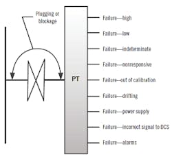
Figure 2: This macro-level failure mode analysis block diagram for a sensor and pressure transmitter (PT) shows the major functions that will typically be broken down into multiple micro failure analyses to fully define the potential failures to be addressed in the function tests.
The percentage of the known, dangerous, undetected failures that are proof tested is called the proof test coverage (PTC). PTC is commonly used in SIL calculations to “compensate” for the failure to more fully test the SIF. People have the mistaken belief that because they have considered the lack of test coverage in their SIL calculation, they have designed a reliable SIF. The simple fact is, if your test coverage is 75%, and if you factored that number into your SIL calculation and test things you are already testing more often, 25% of the dangerous failures can still statistically occur. I sure don’t want to be in that 25%.
The FMEDA approval reports and safety manuals for devices typically provide a minimum proof test procedure and proof test coverage. These provide only guidance, not all the test steps required for a comprehensive proof test procedure. Other types of failure analysis, such as fault tree analysis and reliability centered maintenance, are also used to analyze for dangerous failures.
Types of proof tests
Proof tests can be divided into full functional (end-to-end) or partial functional testing (Figure 3). Partial functional testing is commonly done when the components of the SIF have different test intervals in the SIL calculations that don’t line up with planned shutdowns or turnarounds. It’s important that partial functional proof test procedures overlap such that together they test all the safety functionality of the SIF. With partial functional testing, it’s still recommended that the SIF have an initial end-to-end proof test, and subsequent ones during turnarounds.
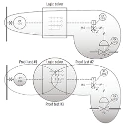
Figure 3: The combined partial proof tests (bottom) should cover all the functionalities of a full functional proof test (top).
A partial proof test only tests a percentage of a device’s failure modes. A common example is partial-stroke valve testing, where the valve is moved a small amount (10-20%) to verify that it’s not stuck. This has a lower proof test coverage than the proof test at the primary test interval.
Proof test procedures can vary in complexity with the complexity of the SIF and the company test procedure philosophy. Some companies write detailed step-by-step test procedures, while others have fairly brief procedures. References to other procedures, such as a standard calibration, are sometimes used to reduce the size of the proof test procedure and to help ensure consistency in testing. A good proof test procedure should provide enough detail to ensure that all the testing is properly accomplished and documented, but not so much detail to cause the technicians to want to skip steps. Having the technician, who is responsible for performing the test step, initial the completed test step can help ensure that the test will be done correctly. Sign-off of the completed proof test by the Instrument Supervisor and Operations representatives will also emphasize the importance and assure a properly completed proof test.
Technician feedback should always be invited to help improve the procedure. The success of a proof test procedure lies in large part in the technician hands, so a collaborative effort is highly recommended.
Online and off-line proof testing
Most proof testing is typically done off-line during a shutdown or turnaround. In some cases, proof testing may be required to be done online while running to satisfy the SIL calculations or other requirements. Online testing requires planning and coordination with Operations to allow the proof test to be done safely, without a process upset, and without causing a spurious trip. It takes only one spurious trip to use up all your attaboys. During this type of test, when the SIF is not fully available to perform its safety task, 61511-1, Clause 11.8.5, states that “Compensating measures that ensure continued safe operation shall be provided in accordance with 11.3 when the SIS is in bypass (repair or testing).” An abnormal situation management procedure should go with the proof test procedure to help ensure this done properly.
A SIF is typically divided up into three main parts: sensors, logic solvers and final elements. There are also typically auxiliary devices that can be associated within each of these three parts (e.g. I.S. barriers, trip amps, interposing relays, solenoids, etc.) that must also be tested. Critical aspects of proof testing each of these technologies may be found in the sidebar, “Testing sensors, logic solvers and final elements” (below).
Difficult things to test
Some things are easier to proof test than others. Many modern and a few older flow and level technologies are in the more difficult category. These include Coriolis flowmeters, vortex meters, mag meters, through-the-air radar, ultrasonic level, and in-situ process switches, to name a few. Fortunately, many of these now have enhanced diagnostics that allow improved testing.
The difficulty of proof testing such a device in the field must be considered in the SIF design. It’s easy for engineering to select SIF devices without serious consideration of what would be required to proof test the device, since they will not be the people testing them. This is also true of partial-stroke testing, which is a common way to improve a SIF average probability of failure on demand (PFDavg), but later on the plant Operations doesn’t want to do it, and many times may not. Always provide plant oversight of the engineering of SIFs in regards to proof testing.
Don’t neglect the inspection
The proof test should include an inspection of the SIF installation and repair as needed to meet 61511-1, Clause 16.3.2. There should be a final inspection to ensure everything is buttoned up, and a double check that the SIF has been properly placed back into process service.
Writing and implementing a good test procedure is an important step to ensure the integrity of the SIF over its lifetime. The test procedure should provide sufficient details to ensure that the required tests are consistently and safely performed and documented. Dangerous failures not tested by proof tests should be compensated for to ensure that the SIF’s safety integrity is adequately maintained over its lifetime.
Writing a good proof test procedure requires a logical approach to the engineering analysis of the potential dangerous failures, selecting the means, and writing the proof test steps that are within the plant’s testing capabilities. Along the way, get plant buy-in at all levels for the testing, and train the technicians to perform and document the proof test as well as understand the importance of the test. Write instructions as if you were the instrument technician who will have to do the work, and that lives depend on getting the testing right, because they do.
A SIF is typically divided up into three main parts, sensors, logic solvers and final elements. There also typically are auxiliary devices that can be associated within each of these three parts (e.g. I.S. barriers, trip amps, interposing relays, solenoids, etc.) that must also be tested.
Sensor proof tests: The sensor proof test must ensure that the sensor can sense the process variable over its full range and transmit the proper signal to the SIS logic solver for evaluation. While not inclusive, some of the things to consider in creating the sensor portion of the proof test procedure are given in Table 1.
| Table 1: Sensor proof test considerations |
| Process ports clean/process interface check, significant buildup noted |
| Internal diagnostics check, run extended diagnostics if available |
| Sensor calibration (5 point) with simulated process input to sensor, verified through to the DCS, drift check |
| Trip point check |
| High/High-High/Low/Low-Low alarms |
| Redundancy, voting degradation |
| Out of range, deviation, diagnostic alarms |
| Bypass and alarms, restrike |
| User diagnostics |
| Transmitter Fail Safe configuration verified |
| Test associated systems (e.g. purge, heat tracing, etc.) and auxiliary components |
| Physical inspection |
| Complete as-found and as-left documentation |
Logic solver proof test: When full-function proof testing is done, the logic solver’s part in accomplishing the SIF’s safety action and related actions (e.g. alarms, reset, bypasses, user diagnostics, redundancies, HMI, etc.) are tested. Partial or piecemeal function proof tests must accomplish all these tests as part of the individual overlapping proof tests. The logic solver manufacturer should have a recommended proof test procedure in the device safety manual. If not and as a minimum, the logic solver power should be cycled, and the logic solver diagnostic registers, status lights, power supply voltages, communication links and redundancy should be checked. These checks should be done prior to the full-function proof test.
Don’t make the assumption that the software is good forever and the logic need not be tested after the initial proof test as undocumented, unauthorized and untested software and hardware changes and software updates can creep into systems over time and must be factored into your overall proof test philosophy. The management of change, maintenance, and revision logs should be reviewed to ensure they are up to date and properly maintained, and if capable, the application program should be compared to the latest backup.
Care should also be taken to test all the user logic solver auxiliary and diagnostic functions (e.g. watchdogs, communication links, cybersecurity appliances, etc.).
Final element proof test: Most final elements are valves, however, rotating equipment motor starters, variable-speed drives and other electrical components such as contactors and circuit breakers are also used as final elements and their failure modes must be analyzed and proof tested.
The primary failure modes for valves are being stuck, response time too slow or too fast, and leakage, all of which are affected by the valve’s operating process interface at trip time. While testing the valve at operating conditions is the most desirable case, Operations would generally be opposed to tripping the SIF while the plant is operating. Most SIS valves are typically tested while the plant is down at zero differential pressure, which is the least demanding of operating conditions. The user should be aware of the worst-case operational differential pressure and the valve and process degradation effects, which should be factored into the valve and actuator design and sizing.
Commonly, to compensate for not testing at process operating conditions, additional safety pressure/thrust/torque margin is added to the valve actuator and inferential performance testing is done utilizing baseline testing. Examples of these inferential tests are where the valve response time is timed, a smart positioner or digital valve controller is used to record a valve pressure/position curve or signature, or advance diagnostics are done during the proof test and compared with previous test results or baselines to detect valve performance degradation, indicating a potential incipient failure. Also, if tight shut off (TSO) is a requirement, simply stroking the valve will not test for leakage and a periodic valve leak test will have to be performed. ISA TR96.05.02 is intended to provide guidance on four different levels of testing of SIS valves and their typical proof test coverage, based on how the test is instrumented. People (particularly users) are encouraged to participate in the development of this technical report (contact [email protected]).
Ambient temperatures can also affect valve friction loads, so that testing valves in warm weather will generally be the least demanding friction load when compared to cold weather operation. As a result, proof testing of valves at a consistent temperature should be considered to provide consistent data for inferential testing for the determination of valve performance degradation.
Valves with smart positioners or a digital valve controller generally have capability to create a valve signature that can be used to monitor degradation in valve performance. A baseline valve signature can be requested as part of your purchase order or you can create one during the initial proof test to serve as a baseline. The valve signature should be done for both opening and closing of the valve. Advanced valve diagnostic should also be used if available. This can help tell you if your valve performance is deteriorating by comparing subsequent proof test valve signatures and diagnostics with your baseline. This type of test can help compensate for not testing the valve at worst case operating pressures.
The valve signature during a proof test may also be able to record the response time with time stamps, removing the need for a stopwatch. Increased response time is a sign of valve deterioration and increased friction load to move the valve. While there are no standards regarding changes in valve response time, a negative pattern of changes from proof test to proof test is indicative of the potential loss of the valve’s safety margin and performance. Modern SIS valve proof testing should include a valve signature as a matter of good engineering practice.
The valve instrument air supply pressure should be measured during a proof test. While the valve spring for a spring-return valve is what closes the valve, the force or torque involved is determined by how much the valve spring is compressed by the valve supply pressure (per Hooke’s Law, F = kX). If your supply pressure is low, the spring will not compress as much, hence less force will be available to move the valve when needed. While not inclusive, some of the things to consider in creating the valve portion of the proof test procedure are given in Table 2.
| Table 2: Final element valve assembly considerations |
| Test valve safety action at process operating pressure (best but typically not done), and time the valve's response time. Verify redundancy |
| Test valve safety action at zero differential pressure and time valve's response time. Verify redundancy |
| Run valve signature and diagnostics as part of proof test and compare to baseline and previous test |
| Visually observe valve action (proper action without unusual vibration or noise, etc.). Verify the valve field and position indication on the DCS |
| Fully stroke the valve a minimum of five times during the proof test to help ensure valve reliability. (This is not intended to fix significant degradation effects or incipient failures). |
| Review valve maintenance records to ensure any changes meet the required valve SRS specifications |
| Test diagnostics for energize-to-trip systems |
| Leak test if Tight Shut Off (TSO) is required |
| Verify the command disagree alarm functionality |
| Inspect valve assembly and internals |
| Remove, test and rebuild as necessary |
| Complete as-found and as-left documentation |
| Solenoids |
| Evaluate venting to provide required response time |
| Evaluate solenoid performance by a digital valve controller or smart positioner |
| Verify redundant solenoid performance (e.g. 1oo2, 2oo3) |
| Interposing Relays |
| Verify correct operation, redundancy |
| Device inspection |
About the author
William (Bill) L. Mostia, Jr., P.E. and ISA Fellow, WLM Engineering Co., can be reached at [email protected].
