How to successfully migrate a control system
Key Highlights
- Preparation is critical to the success of a migration project.
- Execution is important. Identify higher-risk areas and be prepared with alternative plans.
- Run new software in simulation mode, and validate it with operators and process engineers prior to migration.

Greg: There are many practical considerations to ensure efficient and productive control system migration. We’re fortunate to talk with Erik Cornelsen, who is the leading contributor to the ISA’s “Ask the Automation Pros” Q & A articles. Erik is an automation and process control engineer at DPS Group, a Scotland-based system integrator. With more than a decade of experience, he’s worked and lived in six countries, contributing to diverse industrial sectors, including food and beverage, logistics and construction materials. He holds a master’s degree in mechanical engineering from INSA de Lyon in France, and is a chartered engineer, member of the Institution of Mechanical Engineers in the U.K., and is an active ISA member.
To begin, what are the ways to migrate code and what must be checked and tested?
Erik: There are two ways to migrate code. The first is done without rewriting the software (auto-migration), and the second involves rewriting it.
After performing auto-migration, verify that all software blocks are identical to the original program. Pay special attention to functions that may have been automatically converted to a different implementation, potentially altering tag names or addresses, and human machine interface (HMI) connections.
If any portion of the code was rewritten, confirm that its behavior matches the original logic. Give extra attention to sequences and non-standard tuning elements (e.g., debounce timers, filters, custom logics). Remove all obsolete or unused input/output (I/O) from the code. Improve the network architecture in new projects where possible (e.g., implement redundant fieldbuses).
Validate that all analog scaling is correctly normalized and scaled. Test as much as possible during the workshop and factory acceptance testing (FAT), including I/O checks, network communications (e.g., fieldbus, couplers, gateways, firewalls), simulation, HMI trends and alarms.
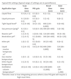
Review proportional-integral-derivative (PID) controller parameters, scan times, type of action (reverse/direct) and control settings. Run a dynamic simulation with proper process relationships and dynamics, and monitor process and PID behavior. Be prepared to fine tune the PID loops.
If other maintenance or cleaning activities are performed during the shutdown, they may also impact the PID settings. For example, if insulation inside a vessel is reduced, the PID controller may need to respond faster and more aggressively, requiring increased gain.
Ensure setpoint values are retained or saved in the new programmable logic controller (PLC) or distributed control system (DCS). Implement a first-scan routine to initialize them as needed.
Configure correct starting values for all setpoints and parameters.
Review signal filtering logic in the software (e.g., moving averages for analog inputs). Add signal filtering, if necessary, especially since new hardware typically updates and processes data faster than older systems.
Create a comprehensive watch table for all I/O. Pay close attention to signals that operate with inverted logic, such as fail-open valves. Perform a full cross-reference of all I/O to ensure every signal is used correctly, and none were overlooked during implementation.
Confirm the type of each variable-frequency drive (VFD) application to ensure correct configuration and control mode. The most common applications are:
- Constant torque: Torque is constant over the speed range, and power is proportional to speed (screw compressors, screw pumps, conveyors, feeders, extruders, hoists).
- Variable torque: Torque is proportional to the square of the speed, and power is proportional to the cube of the speed (fans, centrifugal pumps). In this type of application, it’s easy to save electricity by reducing the motor speed slightly.
Add a ramp to smooth and improve some processes, such as large motors reaching target speed, or smoothing the output of a sensitive PID control loop, such as a compressor.
Check PLC and DCS scan times, as well as the central processing unit (CPU) and memory loads. Check the supervisory control and data acquisition’s (SCADA) CPU and memory loads. Configure Windows's auto-login as operator user in the SCADA client’s personal computers (PC).
Greg: How do you ensure reasonable PID tuning?
Erik: Verify correct PID operation. Consider Greg’s recommended initial tuning parameters (below) from his book, Tuning and Control Loop Performance, Fourth Edition, as a starting point.
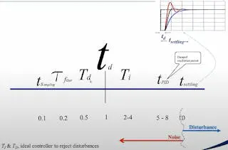
When tuning or studying the existing system, perform a step test to identify the deadtime (td), time constant and process gain. It’s also essential to determine the process type (e.g., first-order or second-order self-regulating, integrating process). The deadtime sets the pace for tuning, and methods such as lambda tuning (modified for near-integrating processes) provide a good first approximation. As suggested by Michel Ruel typical starting relationships are:
Scan-rate: tsampling ≈ 0.1 × td
Derivative time: Td ≈ 0.5 × td
Integral time: Ti ≈ 2-4 × td
Also, note that the ISA Standard form PID derivative time must be less than 1/4 integral time, whereas PID Series form inherently enforces this rule.
Greg: What in the electrical system needs to be reviewed, verified, confirmed and tested?
Get your subscription to Control's tri-weekly newsletter.
Erik: Review the existing power supplies, and upgrade or redesign them if necessary. If multiple power supplies are used, ensure their voltages and reference points are aligned. If possible, consolidate them into a single supply.
Verify compatibility between existing field wiring/terminations and new I/O hardware. Ensure all relevant electrical and control drawings are available and up to date. Confirm that output cards meet required current specifications, especially relay output modules. Ensure all power supplies, racks and backplanes are properly earthed. Verify the presence of proper shielding and shield-termination bars for all analog-related cables (analog inputs, pre-wired connectors, resistance temperature detectors (RTDs), analog outputs).
If the system communicates with multiple SCADA platforms, confirm that communication with each SCADA system is functional and stable. Assess whether hardwired communication between PLCs (via multicore cables and relays) may be simpler or more reliable than network-based communication for certain signals, particularly when communicating with obsolete systems.
Check the polarity of all analog output signals. Use a 500 Ω resistor to convert 4-20 mA signals to 0-10 V during tests that require a current source meter.
Confirm that no unintended or incorrect power supply has been introduced into the existing instrumentation or field wiring. Identify all resistors used for current-to-voltage conversion (e.g., 500 Ω resistors for 4-20 mA to 0-10 V). These may exist in terminal blocks or inside I/O modules. Ensure they’re not removed or bypassed incorrectly during the changeover.
Use a network tester to verify the integrity of all Ethernet connections and cables. The tester should show correct sequencing across all eight conductors plus the ground (1 to 8+ ground (G)).
Set electronic fuses to the appropriate current rating (e.g., 1 amp for 16-channel digital inputs and 2 amp for digital outputs). Leaving them at default high settings (i.e., 6 amp) will prevent them from tripping correctly during faults.
Set the motor breakers to the appropriate motor overload (OL) rating, which can be calculated depending on the motor’s service factor (SF). Typically, if SF is greater or equal to 1.15, then OL is equal to the motor’s full load amperes (FLA) times 1.25, and if SF is less than 1.15, then OL is equal to FLA times 1.15.
Review DC drive settings and reduce the minimum speed if required by the application.
Greg: I highly recommend using ISA Technical report ISA-TR5.9-2023 to find the PID form and structure per ISA Technical report ISA-TR5.9-2023, PID tuning settings units, and whether the PID algorithm is working in engineering units instead of percent signals. Also, use it to determine whether it uses the execution rate in integral and derivative time settings. The PID should be tuned for best process input load response., Then use setpoint lead/lag or 2°of freedom (2DOF) structure setpoint weights and setpoint feedforward to achieve desired setpoint response. I suggest using auto-tuning software. The Astrom relay tuning method is much faster for processes with large lags, and keeps the PID loop in automatic, which is critical for runaway processes.
What can be done to address process considerations?
Erik: Talk to operators and process engineers who work with the equipment daily to gain a solid understanding of how the process functions and what are its key success factors. Use the migration as an opportunity to correct simple existing issues, such as undersized alarm pages or trend display problems. Take photos of all HMI screens and faceplates before starting the migration. Take detailed photos of all electrical cabinets during operation, including gauges, rotary switches and VFD displays showing their actual operating frequencies.
Pay close attention to unstable or runaway processes such as exothermic reactions, oxidation processes or pH-sensitive operations. Understand the expected behavior of the process during startup and shutdown sequences. Develop awareness of discrepancy timers for valves and motors, and be prepared to increase timer values for sticky or slow-reacting processes.
Greg: I highly advocate using a digital twin and first-principle, dynamic simulations with all the deadtimes and lags from process heat and mass transfer, mixing and transportation delays, and instrument responses included. Working with process engineers and operators, advanced control, procedure automation and state-based control should be developed and thoroughly tested.
Top 10 signs a migration project was a huge success
- You become best friends with process engineers.
- A control room is named after you.
- Honorary plaques with your picture are hanging in the halls.
- You have restful days and nights.
- You get to leave early and stay late for a vacation.
- You’re asked to give a talk at a university.
- Students want to become automation engineers.
- Operators cheer when you enter the control room.
- Plant manager takes you out to dinner.
- CEO asks for a Zoom meeting with you.
About the Author

Greg McMillan
Columnist
Greg McMillan retired as a senior fellow at Solutia Inc., now a subsidiary of Eastman Chemical, in 2002. He was an adjunct professor in Washington University Saint Louis’ Chemical Engineering Department 2002-04, and retired as a principal senior software developer at Emerson Automation Solutions in 2024.

Leaders relevant to this article: