Smarter industrial compressor surge protection
Key Highlights
- Dimensionless coordinates are the foundation of reliable surge protection.
- Rectangular coordinates introduce geometric distortion that angular representation eliminates.
- Polar coordinates unlock a unified surge-to-choke control variable spanning the entire operating envelope.
Compressor surge is a phenomenon that can not only disrupt system operation but also cause serious damage. Obviously, such situations should be avoided, but efficiency cannot be sacrificed for the sake of safety. Therefore, the choice of a compressor protection algorithm is critical.
History
Although compressor surge is a highly undesirable phenomenon for industrial installations, it can have particularly catastrophic consequences for aircraft engines. That is why this problem has been the subject of fundamental research since the 1940s.
An example of a comprehensive study with a large volume of experimental data is Report No. 861 of the National Advisory Committee for Aeronautics: "Experimental and Theoretical Studies of the Surge Phenomenon in Continuous-Flow Compressors" from 1946, which remains relevant today. At that time, compressor characteristics were presented graphically in rectangular coordinates, where the horizontal axis represented the mass flow rate of air, and the vertical axis represented the pressure difference.
Later, NASA began using dimensionless analysis in its aerodynamic studies of compressors based on Buckingham's π-theorem—a method used in engineering to group variables into dimensionless numbers to identify patterns in the problem under consideration. This required transforming the rectangular coordinates of the graphical representation of compressor characteristics where the horizontal axis represented the reduced mass flow rate of air and the vertical axis represented the total pressure ratio. It should be noted that total pressure is the sum of static and dynamic pressures.
Prerequisites for the success of existing control methods
While the total pressure ratio is undoubtedly a dimensionless quantity, the concept of a dimensionless quantity for the reduced mass flow rate requires further explanation. For air, that is, for a gas with a constant molecular weight, the reduced mass flow rate can be calculated using equation (1), which includes pressure and temperature values measured at the compressor inlet:

Where ṁ is mass flow rate of air; ṁcorr – corrected mass flow rate; P and T compressor pressure and temperature at the inlet; Pref and Tref – sea level pressure and temperature standards.
Essentially, equation (1) represents the calculation of the Mach number, the fundamental dimensionless quantity in aerodynamics and fluid mechanics, multiplied by some constant.
Applying Buckingham's theorem to a compressor whose characteristics are presented in dimensionless coordinates means that each point in these coordinates has a unique position determined solely by the values of the compression ratio and the Mach number, regardless of the compressor's rotational speed, inlet pressure and temperature, and the molecular weight of the gas. Thus, in this coordinate system, the existence of a boundary clearly separating stable and unstable operating modes of the compressor becomes evident. Such coordinates can be called invariant.
In the face of demands for high efficiency, capacity and output pressure, modern industrial compressors with enhanced aerodynamics, multistage design and adjustable blade angles have a complex structure. Nevertheless, for end-users, they represent "black boxes," requiring reliable protection but equipped with a rather limited set of parameters for controlling and monitoring their operation, such as rotational speed, inlet pressure and temperature, outlet pressure and temperature, flow meter readings and blade angle (if applicable).
The last four decades have demonstrated the exceptional effectiveness of surge protection systems applied to industrial compressors using a limited set of available parameters. There are three such parameters: static pressure at the inlet, static pressure at the outlet and flow rate readings obtained using a differential pressure flow meter. If the compressor is equipped with adjustable vanes, changing their angle can shift the surge line position (although this may not happen, depending on the test results). Choosing the necessary parameters for the protection algorithm is critical. If three parameters are sufficient, there is no need to add a fourth, as its failure would only undermine the reliability of the system.
Industrial compressors have significant advantages compared to aircraft engine compressors:
- The dynamic pressure is always an order of magnitude lower than the static pressure and can be neglected, which simplifies the measurement and calculation of the compression ratio Rc.
- The use of differential pressure flowmeters allows obtaining ΔP readings, which, when divided by the static pressure P at the same point, give a value proportional to the square of the Mach number Ma.

Where: K devise constant; Q volumetric flow rate; p gas density; A cross-sectional area; y specific heat ratio; V gas velocity; a speed of sound.
The choice of rectangular coordinates, whose axes represent the pressure ratio and the calculated value Const2 * (Ma)2, was a key factor in the successful development of algorithms for protecting the compressor from both surge and choke.
However, the most comprehensive approach to describing compressor operation is based on coordinates where one axis represents the compression ratio and the other represents the Mach number Ma, since both dimensionless quantities are, by definition, scaling factors. Therefore, in these coordinates, the characteristics of different compressors can be compared on equal terms. Comparative analysis allows for systematically comparing the complex designs of modern compressors, identifying their similarities or differences, paying particular attention to the position of the limiting boundaries, the shape of the performance curves (how flat or steep they are), and how the curves become flatter as they approach the surge line and steeper as they approach the choking line.
Disadvantages of existing control methods
The proven effectiveness of the surge/choke protection algorithms based on rectangular coordinates has a drawback, as it relies on projections that distort the actual length of the curves, both when assessing the safety margin and when determining the operating range of the compressor. In the case of relatively flat compressor performance curves, as shown in Figure 1, the distortion may be irrelevant as the surge point CSP on the curve is located in close proximity to the surge point SL on the surge line at a given pressure ratio RcOP, which is used to calculate the safety margin, for example, 10%, measured from the minimum flow rate. For a flat curve, the size of its projection onto the horizontal axis significantly exceeds the projection of the safety margin.
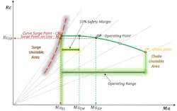
As the slope of the performance curve increases, the CSL point, where surge occurs, shifts away from the SL surge point on the surge line used in the safety margin calculation, and the projection of the curve onto the horizontal axis begins to narrow.
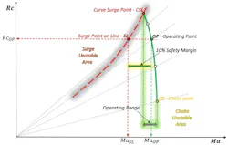
Figure 2 shows a case of a significant change in the slope of the performance curve, whose projection is incompatible with the projection of the safety margin, the size of which is also assumed to be 10% counted from the intersection point of the surge line at a given pressure ratio.
Ensuring maximum safety and efficiency with direct execution
The compressor performance maps provided by manufacturers define the boundaries of unstable operation that must be considered in the compressor control system; the performance curves supposedly describe a predictable change in the operating point movements. However, the control system, processing the necessary input data in real time, constantly monitors the position of the operating point, which, depending on changes in the technological process, does not necessarily have to follow the predetermined curves. Therefore, the rectangular coordinate system can be replaced by a coordinate system using angular values, in which the surge line is defined by a constant angle, and the movement of the operating point can be represented by an angle of rotation. To do this, it is necessary to define a new rectangular coordinate system in which the horizontal axis still represents the Mach number, but the vertical axis is replaced by the Mach number taken from the surge limit line as a function of the pressure ratio.
Get your subscription to Control's tri-weekly newsletter.
Figure 3 shows the transformation to a new transitional rectangular coordinate system, where the surge limit line has become a beam emanating from the origin at a constant angle of 45 degrees relative to the vertical axis, which is true for every case when the operating point reaches the surge limit line, i.e., MaOP becomes equal to MaSL.
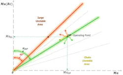
The position of the operating point is determined by the angular dislocation aOP from the vertical axis at given pressure ratio Rc, which can be calculated as follows:

The control variable CV for the anti-surge proportional-integral-derivative (PID) controller can be calculated using the equation:

This anti-surge PID controller works like any other, continuously calculating the "error"—the difference between the desired value (setpoint SP) and the actual value (control variable CV).
The setpoint value serves as a safety margin and can be set, for example, at 10%, which will be equally valid for any slope of the compressor performance curve, since this algorithm tracks the movement of the operating point in a one-dimensional space defined by the angles of rotation and does not depend on its movement in a two-dimensional space of rectangular coordinates.
If the compressor is equipped with inlet guide vanes or has variable geometry, and tests have shown that the surge line depends on the vane angles, then equation (4) needs to be adjusted:

Where f(a) is a function that describes the dependence on the blade angles.
Although the presented algorithm, described by equations 4 and 5 based on angular position control, is simple enough for use in a PID controller and very convenient and understandable for operators when monitoring the complex operation of the compressor in a one-dimensional representation of the control variable CV (%) relative to the setpoint SP (%), especially in cases where it is necessary to switch from automatic to manual control.
Justification for safety margin choice
A drawback of all known control systems is the selection of a safety margin, which is calculated relative to the minimum flow rate. This selection is quite arbitrary and does not correspond to the entire operating range of the compressor, which would allow for justifying the necessary safety thresholds. The chosen safety margin value, based on the minimum flow rate, the same for each performance curve may be sufficient at low speeds but unacceptable at high speeds, where the curves usually have a steeper slope and vice versa.
Typically, compressor manufacturers provide maps containing four to six performance characteristics. However, modern powerful computer processors allow for the addition of extra performance curves using various approximation methods, as shown in Figure 4, where the position of the operating point is determined by two polar coordinates: the angle of rotation aOP and the radius rOP measured from the center. Such a pair of coordinates uniquely defines the position of each operating point and, therefore, allows determining the curve to which it belongs, and the angle of rotation aCP of the point located at the far right of the performance curve corresponds to the choke point or maximum flow rate.
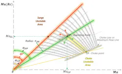
If an angle aCP is present, the control variable CV for the anti-surge PID controller can be calculated using the following equation:

The two-dimensional operating range of the compressor can be transformed into a one-dimensional control variable for the anti-surge PID controller, covering the entire compressor operating range with values from 0% (surge line) to 100% (choke line). Equation 6 can also be used for the choke protection PID controller.
Conclusion
The most accurate and effective methods for protecting the compressor are those based on the angular variables represented by equations 4, 5 and 6. These equations accurately describe the movement of the operating point depending on changes in the technological process and have a linear dependence on the change in flow rate, which simplifies the tuning of the PID controller for surge/choke protection.
In the absence of compressor characteristic curves, relatively simple field tests can be conducted to determine all the necessary data for the PID controller, and then simply set the required safety thresholds as setpoints for surge and choke control.
The selection of safety threshold values is determined by the need to ensure maximum operating efficiency by minimizing unnecessary gas recirculation or air venting without compromising safety. This requires considering the pipeline configuration, check valves, silencers, intercoolers, separators, as well as the response time and size of anti-surge valves, etc. Once the setpoints are determined, they can be used as diagnostic parameters indicating compressor performance degradation or system component failure if these values deviate from the required levels over time.
The advantage of polar coordinates is that the complex process of compressor operation can be represented as a one-dimensional visualization, like that used for monitoring pressure, temperature, etc. in distributed control systems (DCS).
The dimensionless π-coordinates Rc and Ma are scaling factors that allow for the standardization of compressor performance characteristics and play a crucial role in selecting a compressor for specific operating conditions.
About the Author
Roman Bershader
Senior Field Engineer
Now retired, Roman Bershader, worked for more than 30 years as a senior field engineer at Compressor Controls Corporation.
 Leaders Logo
Leaders relevant to this article: