Pumping Station Optimization - Part 2

In the previous installment of this series, I concentrated on describing the "personality" of the pumping process. In this installment, I will talk about the phenomenon of net positive suction head (NPSH) and multiple pump stations. The pressure at the pump suction is called the net positive suction head available (NPSHA). NPSHA is the characteristic teristic of the process and represents the difference between the existing absolute suction pressure and the vapor pressure at the process temperature. The net positive suction head required (NPSHR), on the other hand, is a function of the pump design. It represents the minimum margin between suction head and vapor pressure at a particular flow.
When liquids are being pumped, it is important to keep the pressure on the suction side pressure above the vapor pressure of the fluid. If 15 ºC (60 ºF) water is being pumped at sea level, and the impeller is about one meter below the water’s surface, the NPSHA is about 9.1m (30 ft). It increases if the barometric pressure or the static head rises, and decreases as vapor pressure, friction or entrance losses rise.
The process of cavitation is related to the conservation of energy and to Bernoulli’s theorem, which describe the pressure profile of a liquid flowing through a restriction where, as the fluid accelerates to its maximum velocity, a point of minimum pressure is formed, after which the static pressure recovers. If the static pressure at any point drops below the liquid vapor pressure (Pv), vapor bubbles form, and as it recovers downstream, the vapor bubbles collapse and the sudden condensation forms high energy microjets, that hit metallic objects like bullets. The growth and collapse of the bubbles produce high-energy shock waves that blast small holes in metallic objects, and if the condition lasts long enough, it destroys that part. Cavitation can occur at suction pressures exceeding the NPSHR of the pump. Therefore, only testing for cavitation can positively guarantee that it will not occur.
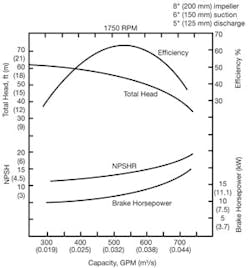
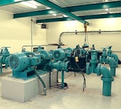
Figure 1 shows the characteristic curves, including the NPSHR of a single-impeller centrifugal pump.
Controlling Multiple Constant- Speed Pumps
Multiple pumps in parallel are used if the variation in flow demand (rangeability) exceeds the throttling range of one pump. The rangeability of individual centrifugal pumps is about 4:1. This means that the flow rate can be reduced to about 25% of pump capacity by either lowering the speed or by throttling a control valve on the discharge of the pump.
When two or more pumps operate in parallel, the combined head-capacity curve is obtained by adding up the individual capacities of the two pumps as a function of discharge head (Figure 2). In such installations, the total capacity of the pump station is found at the intersection of the system head curve with the combined head-capacity curve. Increments of pumping can be added or removed automatically on the basis of flow (see FSH in Figure 2).
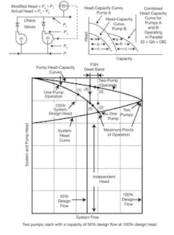
Booster pumps are installed in series and are used to increase the total discharge pressure of the station. When two or more pumps operate in series the total head-capacity curve is obtained by summing up the pump heads at each flow rate (Figure 3). In terms of energy savings, operating pumps in series is most effective when the system head curve is steep. The initial cost of a single, two-speed pump is less than the installation of two pumps in series, but multiple pumps cost less to operate; therefore, the total lifetime cost can favor the use of two pumps.
When constant-speed pumps are used, the booster pump can be started and stopped automatically on the basis of pressure. In this case, an adjustable dead band is provided (in a low-pressure switch PSL) to prevent the on-off cycling of the booster pump. The width of the dead band is a compromise. As the band is narrowed, the probability of cycling increases, but widening it extends the periods during which the booster is operated unnecessarily, wasting energy.
Pump Station Optimization
A pumping system is optimized when it meets the process demand at the least pumping cost in a safe and stable manner. Figure 4 shows such a system where the pump station consists of a variable-speed and a constant-speed pump.
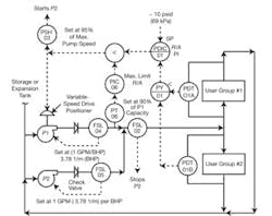
Here, the difference between supply and return liquid pressures is measured for every group of users (PDT), and the lowest reading (at the group of users having the highest demand) is maintained at the set pressure of PDIC-01. This maintains the required minimum pressure for every group of users, so that if any of the supply valves is open at any of the users, this minimum pressure difference will increase the flow through that valve.
When the variable-speed pump in Figure 4 approaches its maximum speed, the high- pressure switch (PSH-03) will automatically start the constant-speed pump (P2). When the load drops to about 90% of the capacity (set on the low flow switch FSL-02), the constant-speed pump is stopped. Extra increments of pumping are started on pressure and stopped on flow.
In other control configurations, the goal is to control the pressure in a supply header (and not the pressure drop across the users). In such installations, all pressure transmitters should be located on main raisers or on the main headers, and they should not be near any major on-off loads, because if they are, all the users will be upset whenever this major load comes on or is removed.
