Under the hood of override control: Part 2
By Harold L. Wade, Ph.D., Wade AssociatesABNORMAL operation in adverse conditions is just a nice way of saying when you-know-what hits the fan. Override control usually refers to applications where one process variable controls the process in normal operation, and during abnormal operation another variable assumes control to prevent encroachment on safety, process or equipment limits. But what if something even worse crops up?A key element of override control, or selector control, is a hardware or software-based selector function, which selects the lower or higher of two or more controller outputs for passage to the final actuator. "Under the Hood of Override Control: Part 1" [CONTROL Dec. '05] reported that the techniques for preventing reset windup of non-selected controllers will perform comparably to reset feedback if the dynamics of the various loops aren’t too dissimilar. Part 2 covers forced initialization under adverse conditions, output tracking, and other methods of implementation, including selection based on error and override control using Foundation Fieldbus.Forced Initialization
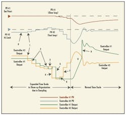
The behavior of the forced initialization method under adverse, but realistic, circumstances (See Figure 1 below and Sidebar Story at the end of this article) was obtained from simulation of a process in which there was a considerable difference in response of the two process variables to movement of the valve. In addition to dead time, Figure 1’s PV#1 exhibits a very slow response to control action, whereas PV#2 responds quite rapidly, both to control action and to disturbances. The simulation shows what can happen under similar, adverse circumstances. Under milder circumstances, such as a slow load disturbance on the faster loop, these conditions would probably not be observed. Even under milder conditions, however, noisy systems can adversely affect the logic that determines the selected and non-selected controllers, and cause unpredictable results.
FIGURE 1: FORCEFUL INITIALIZATION
Possible behavior of the forced initialization implementation method.The discussion above assumes the use of position mode PID algorithms. Some manufacturers use velocity mode algorithms. The incremental change (Δm) of each controller is added to a register value representing the previously desired output position of that controller. The selector is effectively operating between desired positions, not incremental changes. Logic within the selector adjusts the output of the non-selected controller to be equal to the output of the selected controller, plus the gain-times-error of the non-selected loop. In essence, this method should have the same behavior as the forced initialization method using position mode algorithms.Output Tracking
Some systems adjust the output of the non-selected controller to be the same as that of the selected controller, then force the initialization of the controller to this adjusted value. On the next calculation cycle, each controller adjusts its output value by the required increment of change. Since the outputs were previously forced to equality, the selector device then selects between the incremental changes, rather than the desired positions.The following scenario describes the problem of responding to incremental changes, instead of desired positions. Suppose the selector device is choosing the lower of the incremental changes of the normal controller (controlling a slow loop) and the abnormal controller (controlling a fast loop). At set-point, the normal controller issues zero-valued incremental changes, while the other controller, with PV below set point, issues positive-valued incremental changes. The normal controller’s output will be selected, resulting in no change to the valve.Should a disturbance cause the limiting controller to issue a negative-valued incremental change, it will be selected because it’s algebraically lower than the zero-valued incremental change required by the other controller. This will move the valve to a lower position. Suppose the disturbance then disappears before the normal PV has had time to react. The limiting controller will again issue positive-valued incremental changes. The algebraically lower zero-valued incremental change from the normal controller will be selected, resulting in no movement of the valve, even though its position is lower than that required to maintain the normal PV at set-point. This will eventually result in a disturbance to the normal PV, which must experience a deviation from set-point before the valve position can be restored. Had the reset feedback technique been utilized, the correct valve position would have been restored as soon as the disturbance disappeared.Other Implementation Methods
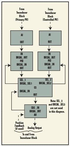
Other implementers have suggested basing the selection criterion on the loop errors, rather than the loop outputs. Depending on the application, the lowest (algebraic) or highest of the error signals would then be passed to a common PID algorithm (See Figure 2 below). This has the advantage of never having a bump in the controller output caused by switchover from one error signal to another. The disadvantage, however, is that there’s one set of tuning parameters that must apply to all affected process variables, even though their response may be considerably different.I’m familiar with a custom implementation that circumvented this problem. Separate logic determined which error signal was selected, and obtained a unique set of tuning parameters from a table for that particular process variable. In essence, this was a scheduled tuning approach.
FIGURE 2: OVERRIDE WITH FOUNDATION
Some systems adjust the output of the non-selected controller to be the same as that of the selected controller, then force the initialization of the controller to this adjusted value. On the next calculation cycle, each controller adjusts its output value by the required increment of change. Since the outputs were previously forced to equality, the selector device then selects between the incremental changes, rather than the desired positions.The following scenario describes the problem of responding to incremental changes, instead of desired positions. Suppose the selector device is choosing the lower of the incremental changes of the normal controller (controlling a slow loop) and the abnormal controller (controlling a fast loop). At set-point, the normal controller issues zero-valued incremental changes, while the other controller, with PV below set point, issues positive-valued incremental changes. The normal controller’s output will be selected, resulting in no change to the valve.Should a disturbance cause the limiting controller to issue a negative-valued incremental change, it will be selected because it’s algebraically lower than the zero-valued incremental change required by the other controller. This will move the valve to a lower position. Suppose the disturbance then disappears before the normal PV has had time to react. The limiting controller will again issue positive-valued incremental changes. The algebraically lower zero-valued incremental change from the normal controller will be selected, resulting in no movement of the valve, even though its position is lower than that required to maintain the normal PV at set-point. This will eventually result in a disturbance to the normal PV, which must experience a deviation from set-point before the valve position can be restored. Had the reset feedback technique been utilized, the correct valve position would have been restored as soon as the disturbance disappeared.Other Implementation Methods
Other implementers have suggested basing the selection criterion on the loop errors, rather than the loop outputs. Depending on the application, the lowest (algebraic) or highest of the error signals would then be passed to a common PID algorithm (See Figure 2 below). This has the advantage of never having a bump in the controller output caused by switchover from one error signal to another. The disadvantage, however, is that there’s one set of tuning parameters that must apply to all affected process variables, even though their response may be considerably different.I’m familiar with a custom implementation that circumvented this problem. Separate logic determined which error signal was selected, and obtained a unique set of tuning parameters from a table for that particular process variable. In essence, this was a scheduled tuning approach.
Tracking Forced Initialization in Adverse Conditions
THE FOLLOWING is a detailed analysis of the possible behavior of the forced initialization implementation method under adverse, realistic circumstances. It was obtained by simulating a process that had a considerable difference in response of the two process variables to movement of the valve. (CLICK HERE to see an enlarged version of this chart.)
- Initial Conditions: PV #1 (slow loop) is at set point. PV #2 (fast loop) is below its limit value. Controller #2 output is above Controller #1 output, thus Controller #1 is the selected controller. Both controllers are reverse acting.
- A sudden disturbance causes PV #2 to rise and the output of its controller to fall below the output of Controller #1. Thus Controller #2 is now the selected controller.
- Controller #2 output continues to fall to correct the rise of PV #2. The PV of controller #1, being a slower loop with deadtime is still on set point, so the Controller #1 output tracks Controller #2 output, but with one sample time delay.
- At some point, due to the corrective action to PV #2, its controller output reverses and become greater than Controller #1 output. Controller #1 is now the selected controller (for one scan cycle).
- Since Controller #2 is now the non-selected controller, its output will be forced to Controller #1 output plus gain-times-error of loop #2. In the example, if PV #2 is above its limit, the error will be negative. Thus, the output of Controller #2 will make a significant decrease, again overriding Controller #1 and becoming the selected controller.
- Controller #1 output tracks (delayed by one sample period) Controller #2 output, plus gain-times-error of loop #1. In the example, the error of loop #1 is still small, so its gain-times-error is essentially zero.
- The effect of a significant decrease in Controller #2 output causes PV #2 to change fairly rapidly. This in turn causes an increase in Controller #2 output, so that it becomes greater than Controller #1. Controller #1 is once again the selected controller.
- Controller #2 output tracks Controller #1 output, plus Gain times Error in loop #2. If by now, PV #2 is below its limit, then the error is positive, so that Controller output #2 will make a jump upward, away from Controller output #1.
- The valve is now significantly depressed from the condition required by either PV #1 or by PV #2. It causes a major upset to PV #1 which due to the slow response of loop #1 can be corrected only slowly.
- When Controller output #1 crosses over the value for Controller output #2, then Controller output #2 is selected. Controller output #1 now makes a jump upward, since PV #1 is below its set point yielding a positive error.
- When equilibrium is retained, unless the initial disturbance to PV #2 is removed, PV #2 will be at it limit value and PV #1 below its set point. Controller #2 will be the selected controller.
[For more information, read: Wade, Harold. L., Basic and Advanced Regulatory Control —System Design and Application, Second Edition, ISA, Research Triangle Park, NC, 2004; or Foundation Specification: Function Block Application Process, Document FF-891, Part 2, the Fieldbus Foundation, Austin, Tex.]
| About the Author |


