Wireless gauging redefines tank level measurement
Key Highlights
- Levels change slowly in tanks that are usually geographically dispersed, making them ideal candidates for wireless sensor networks with minimal impact on control performance.
- Digital and wireless communications improve accuracy by eliminating multiple analog-to-digital conversions inherent in 4-20 mA loops.
- Broad availability of wireless-enabled level and interface sensors allow engineers to install the right measurement at the right location without extensive infrastructure changes.
Large tanks and reservoirs typically have large cross-sectional areas compared to the rate fluids arrive or withdraw. Their levels tend to change slowly, and because of their size, normally cover a large area such as a tank farm. This combination makes them well-suited for wireless sensor networks.
Because of their large cross-sectional areas, accuracy is critical. Digital communications via buses and wireless sensor networks support the need for accuracy by removing the analog-to-digital conversions associated with using analog (4-20 mA) measurements.
Though a basic process control system (BPCS) can control tank levels and inventory, most tank farms, especially for custody transfer, rely on automated tank gauging (ATG) systems to not only control levels, but also aid tasks such as batch control and storage planning. These tasks must follow specific standards and regulations to cover bulk, liquid storage operations.
Key components and technologies of a fluid-storage management system include:
- Sensors that measure level, temperature and pressure in each vessel. They use radar, ultrasonic, capacitance, differential pressure, nuclear, electromechanical, load cells and magnetostrictive technologies. Selecting the appropriate technology is based on the media’s properties—corrosivity, sticky/viscosity or foaming. It also depends on vessel type, and the need to measure one or more interfaces, temperature and area classification.
- Connectivity includes data transmission from sensors to a data-gathering system and control platform.
- Control platform that not only uses BPCS for routine level control, but also specialized ATG systems that have the advantage of also providing track oil movement and operations, inventory control, custody transfer, loss control and mass balance, and volume reconciliation. These volume calculations should follow relevant API standards and other methods suitable for different bulk liquids. The software must be able to manage distinct types of volume tables (strapping tables) with many data points.
- Integration is necessary to use liquid product data from lab samples, such as density and water content. Software should have the capability to use such data, either via direct input from lab systems or by manual operator entry. Direct and derived tank data are distributed through embedding and linking to other office and enterprise software.
- Safety features such as leak detection (interstitial, oil/water), overfill alarms and intrinsically safe (C1D1) sensors for hazardous areas are also necessary.
Get your subscription to Control's tri-weekly newsletter.
Similar to a BPCS, an ATG system is the primary, independent protection layer that continuously prevents tank overfills. When an ATG system functions correctly, it reduces the likelihood of an overfill, so other protection layers won’t need to be activated.
Tank overfills are one of the leading causes of serious safety incidents at bulk liquid storage facilities, but they don’t occur randomly. They’re predictable and preventable. ATG systems help by providing accurate, compensated measurements for the entire facility. Despite this, depending on the process, SIL-rated overfill protection may still be required.
Accurately determining the usable volume in the storage vessel requires knowing the interface location.
Interface level measurement is more challenging, particularly between two liquids, with the oil water interface being the most common. Fortunately, in most cases, this interface is clean, meaning there’s a distinct, sharp boundary between the oil and water layers. In some cases, fine oil-wet solids (clays, asphaltenes) and indigenous stabilizing components in the oil (resins, waxes) accumulate at the interface. This inhibits water droplets from coalescing, resulting in an emulsion or “rag layer” that’s exasperated by upstream turbulence that encourages these challenging components to mingle. I’ve also experienced rag layers because of incorrect (too high) dosing of chemicals meant to clean up the problem of more not always being better.
Measuring the interface between two liquids with a rag layer is challenging because the mixed layer varies in density, confusing standard sensors looking for a clean difference in the property being measured (dielectric, density, viscosity) between the layers. Fortunately, this problem can be overcome with a reasonably accurate interface determination possible by judiciously selecting the measurement technology or a combination of them.
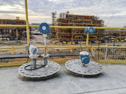
Level measurement options are varied, and almost every supplier provides wireless sensor connectivity. So, you can be sure to install the sensor you need, where you need it to properly operate and manage your facility.
About the Author

Ian Verhappen
Ian Verhappen

Leaders relevant to this article: