Discussing an advanced method of control and protection of compressors
Key Highlights
- The compressor characteristic curve to the left of the surge point creates positive feedback, meaning once the operating point reaches zero slope, it jumps in roughly 0.03 seconds into full flow reversal.
- Control engineers should internalize that approaching the surge curve isn't a gradual degradation—it's a sudden, catastrophic transition.

Greg: We have significant advances offered by Roman Bershader providing the ability to define the surge curve that is essential to prevent surge that seriously disrupts production and reduces compressor efficiency, damages compressor seals and axial compressor rotors.
Roman, what’s your experience with compressor control?
Roman: I retired in October 2020 from Compressor Controls Corporation (CCC), which was acquired by Honeywell in 2023. My retirement followed more than 30 years of demanding work in the field involving frequent business travel around the globe and coincided with my 65th birthday. The company's headquarters were in Des Moines, Iowa, while I myself lived in Atlanta, Ga., where I had moved to 1996. Throughout this entire period, I was a full-time employee of CCC.
The original algorithm employed at CCC was the result of a collaborative effort by three specialists: Naum Staroselsky, Saul Mirsky and Paul Reinke. Upon joining CCC in January 1990, I proposed a modification, subsequently adopted by Staroselsky, that provided truly robust protection. However, it suffered from the following drawbacks: the surge margin was uneven, and the variable used to prevent surging (designated as DEV) was nonlinear in nature, which complicated the tuning of control parameters in both closed-loop and open-loop systems. The value of the DEV variable was calculated as a quantity proportional to the square of the Mach number and was placed in the denominator.
For the first time in many years during my retirement, I found myself with free time, and I was able to dedicate it to writing articles and working on a U.S. patent, which I had been granted.
In my algorithm, the control variable depends linearly on changes occurring within the system. Consequently, the surge margin remains uniform and the tuning of control parameters is simple and straightforward.
Greg: What are the prerequisites for the success of existing control methods?
Roman: The prerequisites for the success of existing control methods lie in the fact that some of them directly utilize the dependence on the pressure ratio, and indirectly on the dependence on the Mach number.
Greg:What are the disadvantages of existing control methods?
Roman: The drawbacks of existing control methods include the uncertainty involved in selecting a safety margin based on the ratio of projections onto the same axes of an orthogonal coordinate system, a choice that depends on changing operating conditions, as well as the inherent nonlinearity of these methods, which significantly complicates the process of tuning PID controllers and implementing open-loop control.
Greg:What is the method for ensuring maximum safety and efficiency with direct execution in a distributed control system (DCS)?
Roman: Maximum safety and efficiency can be achieved through the judicious utilization of the minimum necessary set of available signals combined in a specific manner that is easily configured within a DCS environment.
Greg: What is the justification for the choice of safety margin?
Roman: Outside the control loop, the determining factors are the size and response speed of the anti-surge valve, as well as the length of the industrial compressor's recirculation line.
For the control system—in accordance with recommendations aimed at maximizing efficiency—this threshold should be no less than 10% relative to the "minimum flow" value; however, this approach fails to account for the compressor's full operating range.
A value of 10% may be adopted as a minimum only in cases where a choke limit line is absent; otherwise, the region situated between the surge line and the choke line fully defines the stable operating range, from which the safety margin can be calculated.
Greg: How can you ensure that the operating point never, under any circumstances, crosses the surge curve?
Roman: Setting aside issues related to protection against choke conditions, there are three steps.
- Conducting compressor surge testing to precisely determine the surge line requires the application of specialized methodologies, as well as specific tuning of PID controllers and open-loop control systems designed to prevent the onset of severe surge conditions or full-blown surge. During the surge testing process, the surge line—derived from the compressor's performance maps—is treated merely as a preliminary estimate. The approach toward it is conducted in stages, with continuous monitoring of all input signals. Typically, pressure sensors used in industrial systems lack sufficient sensitivity to gas-dynamic instabilities. However, differential pressure sensors do possess this sensitivity, enabling the detection of "incipient surge" (the most common behavior), "rotating stall" (extremely rare), or a very sharp drop in the flow signal (or a jump upward (also very rare, occurring in approximately 1–2% of cases). The latter is characteristic of axial compressors or centrifugal compressors with a very high pressure ratio (>20).
- Searching for optimal parameters for PID control and open-loop control by simulating various operating modes with varying degrees of anti-surge valve opening.
- Verifying the safety threshold by introducing perturbations into the system.
Get your subscription to Control's tri-weekly newsletter.
Greg: Often, the compressor characteristic curve to the left of the surge line in the below graphic is not known to the user. I developed a first principle momentum balance available as an Emerson Mimic model that reveals this curve and the consequences and protections needed. Here is an excerpt from the Control article “Compressor surge control: Deeper understanding, simulation can eliminate instabilities” (Oct 2018). The following curve provides the understanding often missing.
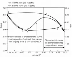
At point B, where the compressor characteristic curve slope is zero, the operating point jumps to point C. The precipitous drop in pressure signals the start of the surge cycle and flow reversal (negative ACFM). As the plenum volume is emptied, the operating point follows the curve from point C to point D, where the slope is again zero, and then jumps to point A. The surge point on the compressor map that is typically a plot of compressor pressure rise versus suction flow is the point where the slope of the characteristic curve becomes zero. Each characteristic curve corresponds to a particular speed or inlet guide vane position.
Plot 2 shows the compressor characteristic curve seen and unseen. Compressor manufacturers often do not show the compressor characteristic curve to the left of the surge point creating a mystery and vulnerability. A first principle model has provided the knowledge as to how negative and positive feedback occurs from the sign and magnitude of slopes seen and unseen in the compressor characteristic curve. The negative slope of the curve to the right of the surge point provides some negative feedback to help with stability.
As the flow decreases, the pressure rise increases creating a greater downstream valve pressure drop and possibly flow. If the downstream valve position continues to decrease, the operating point proceeds to walk to the left from point “A” along the characteristic curve. When the operating point reaches the zero-slope point, it jumps in about 0.03 seconds to a negative flow signifying the beginning of the surge cycle. It is kind of like walking up a mountain and then falling off a cliff.
The compressor characteristic curve to the left of the surge point creates a total characteristic curve that looks like a sign wave. The positive slope immediately to the left of the surge point (maximum compressor pressure rise) creates positive feedback that causes the operating point to jump from point “B” to point “C”, the start of the negative slope. The operating point walks along the negative slope from “C” to “D” the point of zero slope (minimum compressor pressure rise) and then jumps to the right back to the starting point “A”.
If a surge valve is not opened, the process repeats itself. Note the jumps in the suction flow measurement between peaks and valleys are not seen in pressure measurements due to the smoothing by suction and header volumes. The jumps are highly disruptive and damaging due to high axial thrust and radial vibration. Surge cycles damage bearings and decrease efficiency with each surge cycle. For axial compressors, the damage may be measurable after a few surge cycles. The total number of surge cycles provides a good metric of the total loss in compressor efficiency. It is imperative to prevent the surge and to ensure sustained recovery from approaches to surge as well as actual surge.
A surge setpoint offset to the right of the surge curve on the compressor map is computed for a suction flow (surge) controller from the pressure rise across the compressor. The output of the PID surge controller goes to redundant vent control valves. The PID feedback controller is useful to prevent surge for reasonably slow approaches to the surge curve but needs help from feedforward control using flow measurements of downstream users and control logic that is not operating in feedback (closed loop) mode to preemptively position and hold the surge valves open. Since this action is not closed loop and is meant to take over in potentially damaging situations, it is termed an open loop backup. When triggered, the open loop backup puts the PID surge controller in remote output putting the control valves in a position large enough to prevent surge. The open loop backup can be preemptively triggered by a future value computation that predicts the operating point one dead time into the future. The predicted flow is simply the input to a deadtime block plus the change that is the block input minus its output with the block deadtime set equal to the total loop deadtime. Deadtime blocks can also be used to compute a pressure rate of change for a flow rate of change when operating to the right of the surge curve. A small pressure rate of change for a significant flow rate of change indicates an operating point close to the surge curve.
Turning on external-reset feedback (e.g., dynamic reset limit) enables the use of up and down rate limits on the setpoint the PID is manipulating that does not require retuning of the PID. External-reset feedback prevents the integral action from changing the PID output faster than what is happening in terms of the response to the PID output. This is called directional move suppression. By enabling a different move suppression depending on direction opens up many opportunities here and for many other applications. By putting up and down setpoint rate limits on the analog output block for the surge valves and fast readback of actual position, you can have a fast-opening surge valve for surge recovery and prevention, and a slow-closing valve for gradually returning to a more optimum operating position
While all possible means must be used to prevent surge, if there is startup issues not resolved by procedure automaton or a valve, measurement, or equipment failure not protected by state-based control, surge may occur. For recovery from surge, a high rate of change triggers an additional open loop backup that is the input minus the output of the deadtime block divided by the block deadtime that is typically just large enough to provide a good signal to noise ratio.
Top 10 improvements in my process control course
- Kids get in free, except teenagers (they already know everything).
- Anyone who asks a great question gets to teach.
- Real intelligence from first principle models are used to improve artificial intelligence.
- Funny stories about management using industrial internet of things are included.
- There’s rock music in background.
- The visuals are 3-D.
- There isn’t a cameo appearance of president tuning a loop.
- Include more Norwegian Uffda humor.
- Instructor has showered and emptied pockets of sardines.
- More cartoons!
About the Author

Greg McMillan
Columnist
Greg McMillan retired as a senior fellow at Solutia Inc., now a subsidiary of Eastman Chemical, in 2002. He was an adjunct professor in Washington University Saint Louis’ Chemical Engineering Department 2002-04, and retired as a principal senior software developer at Emerson Automation Solutions in 2024.

Leaders relevant to this article: