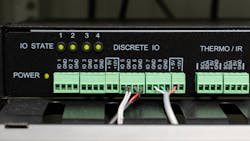
Stan was replacing the safety system’s discrete output modules, which had undergone no more than firmware updates in the decades since the system was installed. He was pleased that his supplier still actively supported the sophisticated safety PLC, albeit a design that was older than his facility. One feature of the original output cards was a “supervised DO” (discrete output) diagnostic that indicated the presence of an open circuit or a short circuit, either of which could compromise critical SIFs (safety instrumented functions).
With the old output modules, he could suppress the diagnostic by installing a dropping resistor on unused outputs; this made the overall “health” of the safety system logic solver easier to discern. He was likewise pleased that with the latest modules and current firmware, he could individually “turn off” unused channels in software.
After completing the upgrade, which included other I/O module replacements as well as CPUs and diagnostic and engineering software, he was dismayed that many of the new discrete output points were showing up as “unhealthy.” He had the techs check the field wiring with a multimeter and all seemed to show the circuits were normal. What was going on that rendered this once-useful diagnostic to show many errors when he could demonstrate he did not have any?
The discrete outputs of a safety system are the principle means that our process safety instrumented systems (SIS) interact with the real world, primarily energizing or de-energizing a “coil,” an inductor in an electromagnetic relay or solenoid valve. Contacts open or close to trip a motor, and solenoids vent (or supply) a pneumatic or hydraulic signal, which in turn—if all goes as designed—force the process to a known “safe” state. Each inductor (coil) in each relay and solenoid valve has a characteristic impedance when “new” and wiring/terminations connecting it to the SIS are pristine. Over time, the coils, wiring and terminations may suffer some corruption, from water ingress, vibration, the stress of environmental extremes, or the normal life cycle of electromechanical devices.
Final elements—the devices that close or open to invoke the “safe” condition and mitigate the hazard—are nearly always the “bad actor” in SIF reliability analyses. That is, they account for the biggest contribution to the dangerous failure probability (PFD). It’s not uncommon that a system aiming for a high safety integrity level (SIL, e.g., SIL 3) either needs very frequent (annual or better) full-stroke testing or routine partial stroke testing, of all parts of the final element, which includes the coils manipulated through the system’s discrete outputs. As for issues that arise between tests, they might go undetected until the next testing interval.
Stan’s decades-old “supervised DO” modules could alert him to some issues between tests, provided someone was paying attention to the diagnostics. Now his new output cards were signaling a spate of problems where he did not think he should be seeing any.
After a call to the system supplier’s engineering and tech support, he was sent a procedure. The new supervision algorithm had configurable limits for high impedance (open circuit) and low impedance (short circuit). While the process was offline, he cycled the outputs through open and closed while collecting the diagnostics. Since the interrogation or “testing” only energized or de-energized the output for a matter of a couple of milliseconds (too brief to affect the physical device), each load (inductor) might not register the same indication.
What he observed was interesting and useful: “ice cube” relays in the motor control center all seemed to have similar high and low impedance limits. So did lever-reset solenoids in pneumatic services, which differed from those in hydraulic services. In all, the site could detect a close correlation among about six different species of inductive loads. What had been a coarse, but useful, “load/ no load” diagnostic could now be capable of detecting more subtle changes, like loose connections or corrosion.
Like the diagnostics of many similar systems, this improvement might only bear fruit if knowledgeable eyes and brains were looking at them routinely. In today’s world, systems dating back a decade or more may not lend themselves to SQL queries, dashboards or Power BI displays, so having procedures and personnel to ensure they are monitored routinely will pay dividends.
About the Author

Leaders relevant to this article:

