This column is moderated by Béla Lipták, automation and safety consultant and editor of the Instrument and Automation Engineers' Handbook (IAEH). If you have an automation-related question for this column, write to [email protected].
Q: I am M. Ulaganathan, working as an instrumentation engineer in the oil and gas domain. I need help related to using resistance temperature detectors (RTDs) to detect liquified natural gas (LNG) leaks and spills.
As per British Standard, we've considered RTD-type devices for monitoring the presence of LNG spills in impounding basins. Now, we require installation details of such RTDs, including whether installation details need to be consider in the course of weld-pad design. Also, how much RTD length needs to be considered, since it needs to be measured at lowest point?
Can you share your experience with using such RTD-type cold detectors in LNG applications? The sharing of installation drawings or photos would be very helpful for my understanding.
M. Ulaganathan
[email protected]
A1: One should not blindly follow standards. You should follow a recommendation only if it makes sense. In this case, the standard makes no sense because using point sensors to monitor the temperature of areas does not! For such purposes, non-contacting thermal imaging is preferred, though their ease of being disabled can be a problem.
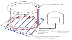
Here I'll describe the fiber-optic distributed temperature sensor (FO-DTS) that can be considered for your application of detecting LNG spills or leaks from storage tanks into your impounding basins. This technology has been around for decades, but only in more recent years has it become reliable and low-maintenance. Such FO-DTS systems include long FO cables that can monitor not only one impounding basin, but a whole tank farm.
LNG is transported and stored at around 4.0 psig pressure and at approximately -162 °C (-260 °F). Therefore, even small leaks or spills will create cold spots as they evaporate (Figure 1).
Figure 2: A continuous distributed temperature sensor measures attenuation and backscattering of laser radiation to infer the temperature at any point along the cable's entire length. Source: APsensing
Fiber-optic thermometers can be single-point, multiple-point or continuous. For your application, the continuous design should be used (Figure 2). This design sends a 10-nanosecond laser pulse through the glass core of the optical fiber. As the optical pulse propagates through the fiber, it undergoes scattering (called Raman scattering) due to structural defects in the glass fiber. In this way, the fiber itself is the sensor and the scattered radiation carries the information on both the temperature and the location of the cold spot. Some of the scattered radiation travels forward and some back to the source, and their ratio is a well-defined function of temperature. This ratio reveals the average temperature of each 1-meter section of the fiber, while the time of the round trip flight of the backscattered pulse indicates the location of any cold spots. This method of location detection is called optical time domain reflectometry (OTDR).
Béla Lipták
[email protected]
A2: This sounds like a completely ill-advised proposition to me.
With a boiling point of -162 °C at atmospheric pressure, how much liquid do you expect to see and for how long if it’s a minor spill? Where would you mount the detector to just be able to catch the transient liquid? This is a job for gas detection.
With a larger spill, a thermal flame detector or thermal imaging camera mounted at some distance would be more useful in detecting the flames. And that’s only useful if people miss noticing the whole plant burning down.
Check out Schlumberger fiber-optic solutions (https://www.slb.com/business-solutions/sensa-fiber-optic-monitoring). They talk specifically about LNG applications including storage and pipelines.
However, I would not want to install a whole lot of temperature elements or a continuous fiber-optic system in a containment area. To me, it's a maintenance nightmare. It will never work effectively. Also, to do this properly would cost a lot of money.
Just because a standard says it should be done doesn’t always mean it’s a practical idea.
There are also various thermal imaging camera solutions (some even have gas concentration measurements via a spectrometer). I would favor non-contact solutions that look at an overall area. Line of sight gas detectors could be a useful addition in this application. You want to be able to cover as much of the area as possible. This will end up being a much more cost effective solution.
In this way, you're not trying to predict where the leak may be.
Simon Luccini
[email protected]
A3: Measuring the temperature of a liquid that's evaporating quickly may present errors due to uneven cooling or vaporization. Furthermore, when trying to detect a leak, you'd need a lot of RTDs since the location of breaks are unlikely to be predictable. Finally, if I remember correctly, the British Standards you're referencing are probably more than 10 years out of date.
But if you insist on using RTDs, the only way to do so would be to have a small support, and place the tip of the RTD perhaps 2 in. from the ground, so the pooled LNG can cover it. I'd recommend that you space them around 3 meters apart, and perhaps use an RTD MUX box to interconnect them. It may work, though I don't believe it would be a reliable system.
My personal preference would be to use an infrared imaging temperature detector as the safest, non-contact way.
Alejandro (Alex) Varga Meder
[email protected]


