Q: I am measuring crude oil components (water, oil, gas) in a three-phase test separator of capacity 3,000 barrels per day (BBD). I designed the orifice plates for the oil and water to be of 1,500 BBD range. However, on actual testing, the oil per well was found to be a maximum of 500 BBD, leading to inaccurate flow measurement. One solution was to use multiple orifices to be swapped before testing each well, knowing approximately the capacity of the well in BBD and taking into consideration the orifice rangeability. Or to use multiple transmitters.
I am thinking of using the existing orifice and transmitter (the existing transmitter rangeability is 1:120) and changing the maximum range of the transmitter's differential pressure to approximately correspond to the well capacity, using the HART communicator. Will this be a good solution to overcome the accuracy problem? Will the accuracy be as good as if I used multiple orifices or transmitters?
Mohamed Amin, director, process control, Comex Commercial Co. / [email protected]
----------
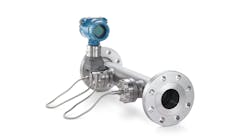
A: In the past, it was common practice to stack and switch transmitters or switch orifice runs to increase rangeability while maintaining accuracy (Figure 1). This is no longer necessary because the differential pressure (DP) cell rangeabilities have increased to as high as 200:1, which provides flow turndowns as high as 14:1.
[sidebar id =1]
As to the total precision of the measurement, one must also consider the errors caused by temperature, pressure and density variations. Therefore, it's important to use smart transmitters that automatically provide that compensation. Where the very best accuracy is required, flow calibration of the complete meter run (the orifice, assembled with the upstream and downstream pipe, including straightening vanes, if any) is recommended. Facilities are available for very accurate, weighed, water-based calibrations in lines up to 24 in. (61 cm) diameter and even larger, and for a wide range of Reynolds numbers.
Table 1 lists the rangeabilities and accuracies of four transmitter design configurations. The accuracy values given in Table 1 assume that the fluid density is constant, the Reynolds number exceeds 10,000 throughout the range (including at minimum flow), the flow is not pulsating, the orifice bore diameter is correctly calculated, and the plate is correctly installed. In that case, the total measurement error is the sum of only the error contribution of the orifice plate and that of the transmitter. The orifice error is less than 1% of the actual reading (AR). The error contribution of a pneumatic transmitter is about 0.5% of full scale (FS), and the error contribution of a smart electronic transmitter is about 0.1% FS.
For detailed coverage of all aspects of orifice-type flow measurement, refer to Chapter 2.21 in Volume 1 of the 5th edition of the Instrument and Automation Engineers' Handbook.
Béla Lipták / [email protected]
[sidebar id =2]
A: My general comment is that many of our instrumentation rules of thumb are more than 40 years old and completely invalid. It may be worthwhile to collect and revalidate these old rules. Also, by solving some of the related equations, one can determine the answers to these types of questions.
Side issue: An erroneous concept is that pressure and temperature (P,T) compensation is only used to calculate mass flow. As shown by the equations below, P,T compensation is (as the name implies) the means to correct either mass or volume flow when the temperature or pressure varies:
Flow (mass) = k*sqrt (ΔP*density)
Flow (volume) = k*sqrt (ΔP/density)
In evaluating the accuracy of orifice flow, first consider transmitter accuracy and rangeability. Modern transmitters have a ΔP rangeability of up to 200:1, which equates to a flow range of almost 15:1. Modern transmitters can detect the ΔP with an accuracy of <0.1% full scale (FS), and require recalibration about every 10 years. The old rule that a second transmitter is to be used if the flow range is greater than 3.5:1 was corect when the old pneumatic ΔP cells were used. In determining the total flow measurement error, transmitter accuracy is not the limiting factor. The total error is a function of many possible error sources.
On orifice installation (apart from the straight run considerations), many orifice plates are just sandwiched between two flanges supplied by the piping group, and the orifice plates are not properly centered. Other installation error sources include impulse tap diameters that are too big, orifice tap location imprecise relative to the orifice plate, and upstream and/or downstream piping is not concentric. The old British Standard BS 1042 (early 1960s) was probably the best document to give a good understanding of the accuracy constraints (I still refer to it now in preference to the successor ISO standards). An orifice installation of this type used to be known as Class C, while if the orifice was installed in carriers with honed piping runs, that was called Class A.
Also, the Reynolds number is a key factor in the orifice calculation, although if it doesn't vary much over the measurement flow range, you don't need to worry about it. The steps in making the calculation are to first do the orifice flow calculation at the various flows of interest, then compare measurements based on these various calculations (using flow = k*sqrt(ΔPx) where x is the flow calculation point. If the generated ΔP is in an acceptable range (e.g. 50 to 400 in.WG), which depends on pressure drop constraints of the installation, and if the proper compensation is used (next paragraph), then the orifice plate does not to be changed.
The latest multivariable transmitters (at least the Emerson one) does calculate the Reynolds number (i.e. does the orifice calcuation, or at least has a multivariable compensation look up table) based on the fluid properties and flowing conditions (e.g. viscosity table based on temperature measurement).
Simon Lucchini, CFSE, MIEAust CPEng (Australia), Chief controls specialist, Fluor Fellow, safety systems / [email protected]
----------
A: Total flow measurement accuracy is affected by ΔP, beta ratio, pipe diameter, use of a flow computer, and straight run distance. A 10:1 in DP range is a real stretch for even a modern ΔP transmitter. Selecting different transmitters with different calibrations addresses only the transmitter uncertainty.
Installation effects increase with Beta ratio. The orifice plates should be inspected and measured. Also, one of the flow standards should be followed. You can use the partial differential uncertainty equations to find the economical approach for improved accuracy. All of this is in the API or IEC literature, both are good.
I've used a temperature-controlled enclosure to reduce the temperature effect. Some users insulate the meter run to stabilize orifice and pipe temperature.
For a decision, the acceptable uncertainty must be defined, as perfect accuracy is never possible. If you can field-calibrate the meter run at operating conditions, the uncertainty would be greatly reduced.
Your decision will probably be clear after determining the cost for the various options you've listed versus the predicted uncertainty with each.
Cullen Langford / [email protected]
----------
A: My recommendation would be to recalculate the pressure drop for different flows using the orifice size as the only non-changing variable. This is the only way to minimize the error of the measurement. If you calculate the flow using, as fixed variables, the pressure drop and the orifice size, the flow values will be very irregular. It's better to use the flows and orifice size as fixed values, to arrive at the predetermined pressure drops, which can be used more easily during recalibration.
The biggest issue is that the crude oil density (specific gravity) must be constant, otherwise the measurement will be in error.
Alex (Alejandro) Varga / [email protected]
This column is moderated by Béla Lipták, automation and safety consultant and editor of the Instrument and Automation Engineers’ Handbook (IAEH). If you have an automation-related question for this column, write to [email protected].