Flow is the basis of material balance—what’s coming into a process and what’s going out. There are several ways to quantify flow: mass (units mass/time), volumetric (units volume/time) and velocity (units linear distance/time). These variables interrelate with one another, and by using other known process variables, flow rate can be calculated through several means.
For example, if velocity is known, and the pipe schematics are known, volume can be derived from Q = vAcs, where Q = volumetric flow (m3/s), v = velocity of the fluid (m/s), and Acs is the cross-sectional area of the pipe (m2). From there, if density is known, mass flow can be calculated from the equation M = ρQ, where M is mass flow (kg/s) and ρ is the density of the fluid (kg/m3).
The concept of developed flow is also important when selecting flowmeters. In process industry settings, fluids pass through obstructions or around bends, and chaotically swirl, disrupting their velocity profiles and creating bias. This chaotic flow takes time to return to equilibrium, leading to a uniform velocity profile called “developed flow” that includes upstream and downstream requirements based on velocity in industrial applications.
Basic measurements, parts and principles
There are many flowmeter technologies available, but many have common anatomical elements and work in similar ways. A typical flowmeter works by altering the stream and measuring how it changes to find the flow value.
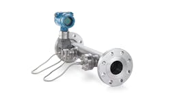
Figure 1: Most flowmeters have three primary parts: an element that's responsible for altering the flow; a sensor that measures the change in the stream and translates the measurement into a value that can be associated with flow; and a transmitter that translates the measurement value into a protocol that the control system can understand. Source: Zachry Group
Flowmeters typically have three basic parts (Figure 1) that can be assembled in different ways:
- Element that's responsible for altering the flow;
- Sensor that measures the change in the stream, and translates that measurement into a value that can be associated with flow; and
- Transmitter that translates a measurement into a protocol that the control system can understand.
Flowmeters are available in insertion- or spool-type designs. Insertion flowmeters are inserted into a nozzle and scale more economically with line sizes. However, insertion flowmeters don’t allow control of the environment surrounding the probe, which necessitates added calibration. Spool flowmeters serve as part of a pipe spool that includes a line of pipe. While they allow more control of the environment around the sensor, spool flowmeters are often quite expensive for larger lines.
When choosing a flowmeter, it’s important to keep some key engineering principals in mind. Every measurement comes with a cost, and the best solution will do the required job for the lowest total installed cost. Even if a flow technology and its installation were free of charge, there are still operating costs, such as pump heads that contribute costs of the measurement. In addition, know your priorities by asking what can be sacrificed and what's truly needed for the process application. Also, repeatability is often more important than accuracy because consistency creates a more efficient process.
Strengths and weaknesses
Because every flow device has limits, the strengths and limitations of each must be evaluated to find the most appropriate choice.
Mechanical flowmeters measure flow as a process flow moves mechanical parts within them. Typically, a mechanical part with a fixed volume is rotated by the stream, and its rotations are counted to infer a volumetric flow rate. Strengths of mechanical flowmeters include low upfront costs, the ability to be manufactured in small sizes, and suitability for extremely low-flow applications. However, mechanical meters may have higher total installed costs, as well as mechanical parts that will degrade over time.
Differential pressure (DP) flowmeters typically introduce a velocity increase and corresponding pressure drop to the system, which pulls some of the pressure (or potential energy) into kinetic energy or velocity. By measuring the pressure drop, velocity can be calculated to find flow.
DP meters are available in many sizes and styles, including orifice plate, pitot tube, venturi, v-cone and wedge. Not only do DP meters offer low upfront costs, but they’re also well understood. However, impulse lines are prone to plugging, and wear and tear on the elements can "invisibly" alter measurement accuracy. Another important limit of DP flowmeters is that flow rate is proportional to the square root of the differential pressure, which limits turndown.
Vortex flowmeters rely on a turbulent flow. When a fluid contacts the shedder bar of a vortex meter, piezoelectronics count the vortices and translate them into flow rate. Vortex flowmeters have low upfront costs, can measure liquids or vapors, are tolerant of droplets in vapor service, and have no stagnant zones. Limitations of vortex meters include the need for a turbulent flow along with a minimum flow requirement to provide any measurement at all. Vortex flowmeters are also generally limited in size to between 0.5 and 12 inches and tend to increase in price with size.
Figure 2: Magnetic flowmeters use the E=vBD equation to find flow by generating a magnetic field and measuring the generated voltage to find velocity. In the equation, E is voltage generated, v is the velocity of the fluid, B is the strength of the magnetic field and D is the distance between electrodes for conductive fluids traveling through a magnetic field. Source: Zachry Group
Magnetic flowmeters determine flow by generating a magnetic field, and measuring the generated voltage to find velocity (Figure 2). Magnetic flowmeters are generally moderate in cost for their size, have an unrestricted flow path, good turndown and are offered with various electrode designs for different services. However, they can only measure conductive liquids, and metallic solutions can generate magnetic fields that can cause inaccurate measurements.
Coriolis flowmeters use the Coriolis force to find mass flow. Most Coriolis flowmeters vibrate two tubes at a natural frequency and measure the change in vibration when the flow stream is introduced. Coriolis flowmeters offer extremely high precision, accuracy and turndown; they measure mass directly; provide a density measurement even without flow; and are insensitive to solids. However, Coriolis meters contain precisely machined elements that are sensitive to corrosive or abrasive surfaces. Other drawbacks include a high permanent pressure loss, relatively low maximum temperature, difficulty with low-pressure gases, and larger sizes that are very expensive.
Ultrasonic flowmeters use ultrasonic beam pulses to measure fluid flow. They're available in two primary types: transit-time and doppler. Transit-time flowmeters use multiple sensor/transmitter elements upstream and downstream on the outside of a line. Because the fluid moves with one beam and against the other, the difference in time for the two beams to travel between the elements is used to calculate the flow rate. It should be noted that transit-time ultrasonic flowmeters require clean service, as particles and bubbles will alter the pulse, and create noise and a loss of signal.
Doppler ultrasonic flowmeters use one sensor/transmitter, which shoots an ultrasonic pulse into the line that reflects off particles and bubbles, and uses the Doppler effect to measure shifts in pulse frequency to infer the flow rate. Doppler ultrasonic flowmeters require particles or bubbles in the stream to function.Ultrasonic flowmeters generally are high precision and turndown, don't restrict flow path, are available in clamp-on type, and are often low-cost. However, when using an ultrasonic flowmeter, again, particulate content must be known. These meters also have significant upstream and downstream requirements, and their sensors must be precisely positioned to be effective.
Optical flowmeters use two lights and corresponding detectors to measure how long it takes for a shape to pass, and employ the equation v = d/t where v is the velocity of the fluid, d is the distance between probes, and t is the time interval between sensor detection. There are two basic types of optical flowmeters: laser two-focus (L2F), which measures the velocity of particles and bubbles moving in the fluid, and scintillating, which measures the velocity of shadows and irregularities caused by turbulent flow. Scintillating meters measure a cross-section area of the flow, capturing the entire 3-D shape of the shadows or irregularities. This makes them relatively insensitive to velocity irregularities, but they do require minimum turbulence (Figure 3). Strengths of optical flowmeters include high precision and turndown, unrestricted flow path, low cost for line size, and they’re ideal for changing fluids. However, optical flowmeters are often overlooked by the industry as a relatively new technology.
Figure 3: The two basic types of optical flowmeters are laser two-focus (L2F) that measures the velocity of particles and bubbles moving in the fluid, and scintillating that measures the velocityt of shadows and irregularities caused by turbulent flow. Scintillating meters measure a cross-section area of the flow, capturing the entire 3-D shape of the shadows or irregularities, which makes them relatively insensitive to velocity irregularities, but they do require minimum turbulence. Source: www.InstrumentationTools.com
Thermal mass flowmeters rely on the ΔH = mCP(T2-T1) equation, where ΔH is enthalpy change/unit time, m is mass flow rate, CP is specific heat, T2 is downstream temperature and T1 is upstream temperature. As a result, heat dispersion between two points in a stream is proportional to mass flow, and by heating an element and placing it upstream of a temperature sensor, mass flow can be measured. Strengths of thermal mass flowmeter are their ability to directly measure mass, availability in insertion type, and high accuracy and precision. However, it should be noted that thermal mass flowmeters require consistent fluid composition of known properties, and typically are only used to measure vapor flow.
Baselines and warning signs
By understanding the available technologies, users can consider which flowmeter is the most appropriate for an application. A good practice is to start with a baseline technology that's inexpensive, and will blanket the majority of the facility’s applications. Differential pressure (orifice plate), vortex and magnetic flowmeters are common baseline solutions. Once a baseline technology is selected, more expensive solutions can be considered for applications that diverge from the facility’s norm. This strategy will help keep maintenance and training costs down.
After an application is defined, if the baseline technology isn't a good enough fit, then other, potentially more expensive options can be considered. The following are some of the warning signs that a specialized flow technology might be necessary:
- High accuracy or turndown requirements,
- Extremely low flow,
- Large line size,
- Variable/unknown composition,
- Dirty/erosive surface,
- Multiphase flow,
- Short upstream/downstream straight pipe runs,
- Low available pressure drop,
- Bidirectional flow, and
- Crystallization concerns.
Right choices for the real world
So which flow technologies are the best options for which process applications? It depends on the operating characteristics and goals of those processes.
For instance, the aim of custody transfer is to track how much important chemicals, products or other fluids are leaving or entering an area, which could be for mass balance or point of sale. Inaccuracy means lost revenue, so accuracy is more important, and turndown is a plus. Options include:
- Turbine/positive displacement flowmeters have high accuracy and turndown, but moving parts mean more maintenance, so they're used less now.
- Coriolis flowmeters are the most accurate, but even though they're pricey for big lines, they're often the first choice for lines less than 8 inches in diameter.
- Ultrasonic flowmeters also have high accuracy and turndown, so they're economical for large lines, and are used more often lately for such applications.
- Scintillating optical flowmeters have high accuracy and turndown, and they're economical for large lines, too. They aren't a standard yet, but may become one soon.
Injection quills add tiny flows of costly, commodity chemicals to larger streams, or are used in labs with low flows and small pipes. At extremely low flows, the regimes are laminar, but there's variance across profiles. This makes injection quills and other low-flow applications difficult for velocity-based flow measurement, especially as flow approaches zero. Options include:
- Positive displacement because their mechanical rotation isn't very sensitive to flow profiles.
- Coriolis that comes in small sizes, has very high turndown, and measures mass, so velocity isn't very important.
Large air duct processes typically involve intakes to large compressors, operate at low pressures that favor instruments with minimal pressure drops such as insertion or no flow obstructions; have huge line sizes, often with square profiles that favor insertion types or external sensors; and are exposed to particles in the air such as dust solids and condensates that favor devices that are resistant to plugging. Options include:
- Insertion-type DP pitot tube (purged) flowmeter, which measures velocity at a representative point that may be difficult to obtain. Purge devices may protect the unit from plugging, but they also require a constant expense for air pressure.
- Low-pressure loss DP venturi (purged) flowmeters, which deal with condensate well, are often used on suction of compressors, but are costly at large line sizes, and also require a constant operating cost.
- Clip-on ultrasonic is inexpensive for most line sizes; non-contact, so there's no pressure loss, so they may seem attractive, but they have high upstream-downstream straight pipe run requirements and may be difficult to place on a square duct.
- Insertion-type thermal mass flowmeter is also inexpensive for most line sizes, less sensitive to turbulence, and benefits from air's well-known properties.
As the vapor garbage disposals for refineries, flares can have a huge range of compositions, environmental requirements that require accuracy and need premium turndowns to cover flows from a trickle to the whole plant venting at once. Big lines for flaring mean they favor devices that scale well with line size, while handling many vapor densities and properties, which means they also need technologies that are insensitive to those vapor properties. Options include:
- Ultrasonic flowmeters scale well with size, have great turndown and accuracy, and aren't heavily influenced by fluid properties if the stream is relatively clean.
- Optical flowmeters scale well, have great turndown and accuracy, and aren't heavily influenced by fluid properties.
Wastewater/high solids feeds are only mostly liquid, so plugging is a concern that favors open flow paths and no stagnant zones, while erosivity is a concern that favors hardened flow elements or no element in the stream. Options include:
- Magnetic flowmeters are great for conductive liquids, work with straight paths, and have erosion-resistant electrodes.
- Doppler ultrasonic flowmeters thrive in areas with particulates, and also work with straight flow paths.
- DP wedge flowmeters with hardened, indirect impact surfaces for maximum erosivity resistance also feature the ability to handle non-conductive fluids.
- Optical (L2F) flowmeters thrive in areas with particulates, and also work with straight flow paths.
Brownfield process applications typically need to add a flow sensor to an existing line, can't take up much space, and have tight piping with very short upstream and/or downstream lengths. Options include:
- Mechanical flowmeters that count volumes directly, but have moving parts requiring more maintenance.
- DP V-Cone flowmeters designed to condition flows as a part of measurement, and are resistant to entrained particles.
- Coriolis flowmeters that measures mass directly, and are insensitive to flow profiles.
References
- www.instrumentationtoolbox.com
- www.engineeringtoolbox.com
- Liptak, Bela, et al. Instrument Engineers’ Handbook, 4th edition, Chapter 2, CRC Press, 2003
About the author:
Eric Lofland is senior engineer in the Instrumentation and Controls Dept. at Zachry Group. He can be reached at [email protected]