Satish Mathur is an engineering supervisor in the Process Department of Bechtel India Pvt Ltd.
The amount of flow through a control valve depends on the size of the valve, the pressure drop over the valve, the stem position and the flow properties. A simplified design equation for non-flashing liquids, ignoring the effect of the connected fittings, can be derived from References 1, 2 and 3 as
where F = fluid flow through control valve, Cv = valve flow coefficient (at full open condition); x = valve stem position, f(x) = fraction of valve size coefficient at any given valve stem, opening indicating the inherent flow characteristics of the valve; ∆Pv = pressure drop across the control valve and sp.gr. = specific gravity of the fluid. (More detailed equations are available in the standards (References 1 and 2) and publications of the control valve manufacturers (Reference 4), which also address flashing liquid services.)
See also: Does valve size matter?
The most common valve characteristics are equal percentage, linear, and quick opening. Due to distortion in valve characteristics at the extreme conditions of full open and full shut, as well as the performance of the valve actuator and spring, the usable valve opening range is less than 0 – 100%. Typically, it is about 10% to 90%. Distortion is also due to system losses, which vary the pressure drop across the valve and result in a valve characteristic different from the valve’s theoretical characteristics 6.
The present analysis is based on the linear characteristic, which is often the choice where constant control valve gain (the magnitude ratio of the change in flow through the valve to the change in valve travel under conditions of constant pressure drop) is required for accurate control of parameters such as level or flow.
Develop the system head curve
To specify the pump and control valve, we first need to develop the system head curve, which is the head required (m) to be developed by the pump at different flows (m3/hr), ignoring the losses across the control valve.
Figure 1. A simple system includes static (height) and dynamic (piping) losses that are represented by a head curve (Figure 2).
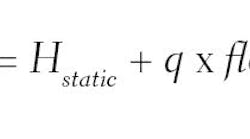
For systems comprising of static and dynamic losses, such as shown in Figure 1, the system head curve can be represented as follows:
Where, HCstatic = a constant, sum of the static head and pressure difference between source and destination, and q is a multiplying factor between dynamic head and square of flow, which is a constant in turbulent flow condition. Figure 2 shows a system head curve developed using Hstatic = 50 m and q = 0.009 [m head/(m3/hr flow)].
Figure 2. The head curve for the simple system in Figure 1 might look like this.
Define the flows
The next step is to define the required operating flow range. The maximum and minimum flows should be defined at a very early stage, as they not only affect the selection of the control valve, but also the minimum required pump head, as will become clear later in this article.
Maximum flow: Generally, operation at the design capacity is considered 100% flow. Increase above 100% is expected to be temporary for purposes such as making up a drum level that has depleted due to a process upset. Such margins will depend on the nature of disturbance, but for level and flow control they are generally about 10-15%. For restoring normal conditions in a distillation column, the margin for reflux control may be even higher at 20%. The maximum for the control valve will therefore be 110-120% of the design, depending on nature of corrective action required.
Minimum flow: Processes are expected to generally operate at 100% (design capacity) for the best overall efficiency, however they may have to be designed for operating at less than 100% for significant periods, for example, due to limitations of feed availability or product offtake. Generally, the turndown condition is defined at the design stage so all components of the process can be suitably specified. In this case, from the control point of view, the turndown condition should be treated like an alternate operating case.
Margin below the turndown is required for reasons similar to those for maximum flow. A temporary high level in a drum may have to be restored to normal by reducing intake flow into the drum during turndown operation of the process. Therefore, the control valve minimum has to be computed considering about -10-20% below the steady-state turndown, with the margin depending on the nature of corrective action.
See also: Retrofit projects: Getting flows right
The extreme maximum and minimum flows defined above should be matched to the control valve’s usable limits of 90% and 10% openings to fully use the valve’s capability, while ensuring that control valve is not made to operate outside its recommended opening.
Using the control valve Equation 1 for minimum flow and maximum flow rates, a relation between the control valve ∆P at minimum flow and ∆P at maximum flow can be created. For valves with linear characteristics, the relation will be:
Characterize the system
A common practice in pumped systems is to allow a minimum of 10-15 psi for the control valve pressure drop. Using Equation 3 and the control valve pressure drop at max flow, one can calculate the control valve pressure drop at min flow, as well as at normal (100%) flow. System head plus the control valve head for the conditions of min flow and max flow are plotted in Figure 3. The straight lines are all based on 115% max flow with a control valve head loss of 10 m water column (WC) at max flow. Lines for various minimum flow cases (30%L, 35%L, 40%L, 45%L and 50%L) are plotted.
These lines should fall on the characteristic curve of a centrifugal pump, since system head plus control valve loss has to equate to the pump head. However, some of these lines can be seen to slope downward toward lower flow rates. This is unlike the shape of a centrifugal pump characteristic curve, which slopes down towards rising flow conditions. Only one of these lines will best match the pump curve. In this case, only at 45% and higher minimum flow is the head requirement seen to reduce with increased flow.
In a second example, the above are calculated based on a control valve with 30m WC loss instead of 10m WC loss at the maximum flow. Loss at minimum flow is computed following the above steps, and the lines (30%H, 35%H, 40%H, 45%H and 50%H) are also plotted in Figure 3. Here, even for the 30% turndown case, the head is reducing with increased flow. In this case, the system head plus control valve head will track the pump curve to an even lower value of minimum flow than the case above.
Figure 3. Plot the system head plus the control valve head for the conditions of min flow and max flow, and connect them with a straight line. These examples show the effects of low (L) and high (H) pressure losses across the valve at 100% flow with minimum flows of 30% to 50%.
Understand the pump
The effect of flow turndown on pump duty can be evaluated if the shape of the pump characteristic curve is known. Consider a parabolic-type pump curve given by the equation:
where a, b and c are constants. A typical pump model will offer a family of pump curves for different impeller diameters. The vendor’s supplied curves should be used for engineering, however, the flow versus head curves for different impellers can be approximated using the law of affinity:
where n is the ratio of the diameters, such as n = D2/D1.
The curve with minimum n that meets the system plus control valve head at min, normal and max flow conditions represents the optimum pump selection. Curves are plotted in Figure 4 for 25.6%, 28.8%, 32.9%, 38.3%, 46.0% and 57.5% minimum flow cases (with 115% as the maximum flow in all the cases) by simultaneous solution of the system head (Equation 2), control valve (Equation 3) and pump family of curves (Equation 5) to get a diameter ratio n. The constants used for the pump curve were a = 200, b = -0.05 and c = -0.001.
Figure 4. Higher flow turndown comes at the cost of higher control valve loss and, therefore, a higher pump head. In this example, about 45 m less pump head is required at 100% flow if the control valve minimum flow requirement is changed from 25.6% to 57.5%.
One valve or two?
As seen in Figure 4, about 45 m less pump head is required at 100% flow if the control valve minimum flow requirement is changed from 25.6% to 57.5%. In conclusion, higher flow turndown comes at the cost of higher control valve loss and, therefore, a higher pump head. This is also explained in Reference 3. The lower control valve loss at normal (100%) flow means continuously spending less energy since system is expected to operate most of the time at 100%.
It is clear from the above that extreme care should be taken in deciding the min controlled flow and to not aim for some extremely low flow if it’s not really needed. If a very low flow condition is required on an infrequent basis, see if it can be handled using a small manual valve in the bypass of the control valve. Alternately, a smaller capacity control valve, sized specifically for the very low flow condition, can be provided in the bypass of the main control valve. For example, where valve A is the original valve covering 57.5% to 115% flow range, simultaneous computation of Equations 2, 3 and 5 shows that a small control valve B can be provided in parallel to cover 28.8% to 57.5% flow range. Using the same impeller diameter ratio n chosen for the larger valve A, the two control valves can control throughout 28.8% to 115% range of the flow while consuming about 40 m less pump head at 100% flow condition. Over the lifetime of the plant, the energy saved may justify the additional cost of the smaller control valve.
A simple step-by-step
In summary, the recommended steps for pump and control valve system design are these:
Prepare system head curves. If the destination pressure is variable, prepare curves similar to Figure 2 for each destination pressure. Then prepare an overall system curve (Figure 5), connecting the extremes of maximum flow, maximum destination pressure on one side with minimum flow, minimum destination pressure on the other side.Figure 5. If the destination pressure is variable, prepare curves similar to Figure 2 for each destination pressure. Then prepare an overall system curve connecting maximum flow, maximum destination pressure on one side with minimum flow, minimum destination pressure on the other side.
- Maximum flow: Pump to provide not less than the specified head 10-5 psi (7-10 m WC) at this flow condition (otherwise the control valve will have to open above the maximum recommended opening, which is not desirable).
- Normal flow: Pump should have the highest efficiency at the specified flow and head conditions.
- Minimum flow: The excess above the minimum flow head should be as low as is available from the pump (otherwise the control will have to throttle below the minimum recommended opening, which is not desirable).
The pump vendor should also be asked to supply a family of curves in the range of 110% - 90% of the head to help in optimizing the selection of the pump
Figure 6. Match the pump curve at maximum flow, normal flow and minimum flow, with best efficiency at normal flow. If the selected curve doesn’t touch all three duty points, consider increasing the control valve minimum flow and adding a second, smaller valve in parallel for low flows.
- Increase the control valve’s minimum flow. Re-compute the required pressure drop at minimum and 100% flow using equation 3 and recreate Figure 3. Then superimpose a curve from vendor’s family of curves. In this case, a second control valve in parallel will be needed for the low-flow rate operation.* Match the duty points with vendor's curve by increasing the control valve pressure drop from 10-15 psi (7-10 m WC) at maximum flow. This will avoid a second control valve, but have higher energy losses.
Evaluate between the two options and decide the most economical.
- ANSI/ISA-75.01.01 Standard, Flow Equations for Sizing Control Valves.
- ANSI/ISA–75.11.01 Standard, Inherent Flow Characteristic and Rangeability of Control Valves.
- “A Rational Approach to CV Sizing,” Ind. Eng. Chem. Res., 1990, 29, 700-703. William L. Luyben.
- Emerson Control Valve Handbook.
- Pumping Systems Tip Sheet #10, March 2007. U.S. Department of Energy.
- Control Handbook, B. G. Lipták (chapter 36, Applying Control Valves).


