Learn the basics of PID
Proportional-Integral-Derivative (PID) control is used in more than 99% of the loops for chemical, pharmaceutical, and food and beverage production. PID has proven to be capable of the best load rejection by using the best tuning and the extensive flexibility of functionality offered by the PID structure and options, most notably external-reset feedback. Bohl and McAvoy enlightened us about it in a 1976 landmark paper, “Linear Feedback vs. Time Optimal Control, II. The Regulator Problem” (Industrial & Engineering Chemistry, Process Design and Development, Vol. 15, No. 1, 1976, p. 30-33).
The opening challenge with PID control is recognizing the effect of PID form, structure and tuning units. Going from proportional band in percent to a dimensionless PID gain, and from a reset in repeats per minute to seconds, are recognizable factors to address, but are sometimes overlooked. Less understood is how to convert tuning settings to the ISA Standard Form from the Series (Real) Form in analog control and early DCS systems, and from the Parallel (Independent) Form in the control literature, converting integral and derivative gains to reset and rate times.
Especially noteworthy is that in the Series Form, the derivative time (rate time) could be set as large as the integral time (reset time). Some older tuning methods even suggested this. Interaction between these modes in the time domain by Series Form would inherently prevent oscillations by effectively reducing integral and proportional action thru interaction factors. When using the ISA Standard Form, the rate time has to be set less than one-fourth the reset time to prevent oscillations. Many users have made mistakes in system upgrades by not paying attention to the changes in form and units by the even the same system supplier.
Literature can’t always be taken literally
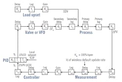
The literature is also misleading by nearly always citing a process deadtime, process time constant and process gain when the actual dynamics depend on what's in the automation system (Figure 1). PID tuning needs to use the open-loop gain, open-loop time constant (primary time constant), secondary time constant and total loop deadtime. The open-loop gain is the product of the valve or variable-frequency drive (VFD) gain, process gain and measurement gain. The resulting gain is dimensionless for self-regulating processes and has units of 1/sec for integrating processes. The open-loop time constant is the largest time constant in the loop, and hopefully in the process to slow down disturbances on the process input. Unfortunately for flow, liquid pressure and surge control, the largest time constant is in the automation system, slowing down the ability to see and correct for disturbances.
Figure 1: For a first-order approximation, the total loop deadtime θ0 ≈ θV + θS + θP + θm1 + θm2 + θC + Y*τV + Y*τS + Y*τm1 + Y*τm2 + Y*τC1 + Y*τC2. The Y fraction of small lag that is equivalent to deadtime is a logarithmic function of the ratio of the smallest to largest lag (Y=0.28, 0.88 for ratios of 1.0 and 0.01, respectively). KV is the slope of the installed flow characteristic, and τ0 is the largest lag in the loop, hopefully τp. For self-regulating processes, K0 = KV * Kd * Km; for near-integrating processes, Ki = KV * (Kp/τp) * Km.
The secondary time constant is the second largest time constant in the system, often in either heat transfer surfaces or the automation system. The total loop deadtime is the sum of all the deadtimes and the fraction of all the small time constants creating equivalent deadtime. To better communicate, realize the implications of dynamics, and achieve the best PID, see the Control Talk blog post, “Understanding terminology to advance yourself and the automation profession.”
Another major point of confusion is lack of recognition that nearly all disturbances are on the process input and not the process output, as is commonly depicted in the control literature. Also, except for flow and liquid pressure control, the response is near-integrating or true integrating, requiring integrating process tuning rules and an overshoot by PID output of its final resting value that's the output after completion of the response to a load or setpoint change. What's in the literature are self-regulating processes with a process time constant-to-deadtime ratio for dynamics that rarely gets below 0.25 or above 4, leading to Internal Model Control. While these dynamics are infrequent in chemical plants except for flow loops, they're applicable to pulp and paper and mining plants due to a lack of back mixing.
You can convert back and forth between self-regulating and integrating process dynamics by realizing that open-loop, near integrating process gain is simply the open-loop self-regulating process gain divided by the open-loop time constant (Figure 1).
Integrating process tuning rules are designed to provide the best disturbance rejection. This can be tested by momentarily putting the PID in manual and making the largest step change in PID output that the operator is comfortable with (e.g., 5-10%). Changes less than 1% typically show a much slower and possibly no response due to actuator and positioner sensitivity limit, as well as valve backlash and stiction.
Feedforward and ratio control are underused
Nearly all control loops end up manipulating a flow either directly by cascade control, where a primary process controller manipulates a secondary controller setpoint, or by directly positioning a control valve. Here, we consider changes in speed as effectively causing changes in flow even in sheet lines. Nearly all fast disturbances are changes in flow, and decoupling signals from interacting loops are changes in manipulated flow. The needed end result is a ratio of the manipulated flow or speed to a leader flow or speed that is a disturbance from an uncontrolled (wild) flow, a manipulated flow by another loop, or a deliberate change in production rate or composition.
If there's no secondary controller, flow feedforward is used primarily via a feedforward summer. The most common example is steam header letdown pressure control, where feedforward signals from steam users and suppliers and decoupling signals from other header letdown valves are summed together in a feedforward summer. Signal characterization is used where there are not flow measurements to convert a percent valve signal to a percent valve flow per installed flow characteristics. For compressor surge and pressure control, feedforward summers are used for decoupling between headers and disturbances from downstream users, since the controller outputs go directly to valves and vanes. Secondary flow controllers would be too slow in these cases.
Most process equipment involving liquids can benefit from secondary flow controllers. Here, ratio control is used to achieve and correct as needed the ratios of flows seen on a process flow diagram (PFD). Many processes, particularly distillation columns, are started up on ratio control. The ratio is corrected by a bias to the secondary controller setpoint for volumes with some mixing, such as crystallizers, columns, evaporators, neutralizers and reactors. For sheet lines and extruders, the ratio setpoint is corrected.
Dynamic compensation must be applied to a leader flow before it becomes a feedforward signal or ratio controller input flow. To make sure a change in manipulated flow arrives in the process at the same place at the same time as a change in leader flow, a deadtime and lead/lag (L/L) block is used. If the correction arrives too soon or too late, inverse response and sequel disturbance are created, respectively. Unfortunately, tuning software packages may not identify the deadtime and L/L settings. The block deadtime for dynamic compensation is the deadtime in the disturbance variable path minus the deadtime in the manipulated variable path. The L/L block lead time is the lag time in the manipulated variable path, and the L/L lag time is the lag time in the disturbance path. The lag time should be at least one-fourth the lead time to prevent noise. Model predictive control (MPC) does this identification and correction for the user, which, along with ability to avoid tuning override controllers, are the principal reasons why MPC replaces PID for even a small applications where a PID could suffice (e.g., one decoupler, one feedforward and one constraint).
After good load disturbance rejection is achieved, good setpoint response is possible by using a filter lag equal to the reset time, or a structure with proportional and derivative action on the process variable and Integral action on error (PD on PV and I on E). If you want a faster approach to setpoint, you can use a L/L instead of a filter on the setpoint with the L/L lag time equal to reset time, and the L/L lead time equal to one fourth the lag time, or a two-degrees-of-freedom (2DOF) structure with the setpoint weights for proportional and derivative action set equal to 0.5 and 0.25, respectively. Most of the literature concentrates on setpoint response, ignoring load response and advantages of lead/lag and structure options.
Remember external-reset feedback
The other thing most users are not aware of is the incredible capability offered by external-reset feedback (e.g., dynamic reset limit) to:
- Suppress oscillations from a slow secondary loop, slow control valve or VFD, and deadband and resolution limits.
- Provide directional move suppression to prevent unnecessary crossings of split-range points; enable gradual optimization and fast getaway by a VPC, a fast-opening and slow-closing vent, or recycle valve for surge control; and minimization of upsets to other loops.
- Achieve deadtime compensation as good as a Smith Predictor or MPC without having to know the open-loop gain or time constant, or needing to provide a special operator interface. Deadtime compensation is achieved by simply inserting a deadtime block in the external-reset feedback path and tuning the PID much more aggressively (e.g., reset time can be decreased by an order of magnitude if deadtime is accurately updated).
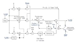
Figure 2: All signals are percent-of-scale in the PID algorithm but inputs and outputs are in engineering units. For structures with no P action, gain is zero for the proportional mode. Gain is one for the integral mode, and equal to the PID block gain setting for derivative mode. Bias is used as input to the reset time filter block when there is no integral action. Bias is the PID output when the error is zero, and is filtered by the reset time whose best setting is reduced to be about the deadtime. External-reset feedback (ERF) is, for example, secondary loop process variable (%PVs) or fast valve readback.
Figure 2 shows the only known time domain block diagram that details the ISA Standard Form with the ability to achieve eight different structures and true external-reset feedback with the positive feedback implementation of integral action.
Relative gain analysis is a powerful technique for accessing the type and degree of interaction. The relative gain for a given loop is its open-loop steady state gain with the other loops open divided by its open-loop steady state gain with the other loops closed. The given loop is open for the tests with the other loops open and then closed, to show response without and with interaction, respectively. A loop is considered open if the mode is manual or remote output.
For integrating processes, the process variable is translated to a rate of change, so a steady ramp rate gives a steady state. The relative gain is dimensionless, and thus doesn't depend on the engineering units of the loops involved. The relative gain doesn't change when a flow ratio rather than a flow is manipulated. Operating point nonlinearities will affect the analysis but not changes in time constants and deadtimes. Ideally, pairing of loops should have a relative gain close to one or slightly higher. Negative relative gains are disastrous. Often, the relative gain array can be simplified to show the relative gains for the four pairs possible between two controlled variables and two manipulated variables (2 x 2).
If you want a comprehensive, concise view of how to achieve the best PID control, and gain an excellent understanding of everything else needed for a successful automation project, look for the McGraw-Hill handbook Process/Industrial Instruments and Controls, Sixth Edition, due out early in 2019. The handbook covers the design, installation, calibration, commissioning and maintenance of every part of an automation system, concluding with a list of best practices for each of its 100 sections. Meanwhile, the sidebar provides best practices excerpted from the handbook’s PID Basics section.
Gregory K. McMillan, Control columnist and Hall of Fame member, can be reached at [email protected], and P. Hunter Vegas, engineering manager, Wunderlich-Malec Engineering, can be reached at [email protected].


