
Modbus is a communication protocol for transmitting information between electronic devices over serial lines (original version) or via the Ethernet, and is commonly used in process and factory automation. While it’s an open protocol and anybody can use it, “Modbus” is a registered trademark of Schneider Electric USA, Inc. (current owner of the Modicon brand). The Modbus.org organization was created to further the use of Modbus and Schneider Electric has been a partner in it. This article is an introduction to Modbus and its basic functions—Modbus.org has extensive coverage on Modbus, the specifications for the various types of Modbus, software, testing, interface code and more. The Internet also has available tutorials and specific information on individual device Modbus implementations.
Modbus serial protocol (the original version) is a master/slave protocol, e.g. one master that controls the Modbus data transactions with multiple slaves that respond to the master’s requests to read from or write data to the slaves. Modbus TCP, also known as Modbus TCP/IP, uses a client/server architecture. These network architectures are shown Figures 1 and 2.
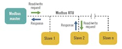
Figure 1: In a standard Modbus serial network, there is one master and up to 247 slaves, each with a unique slave address.
In a standard Modbus serial network, there is one master and as many as 247 slaves, each with a unique slave address. Modbus TCP is typically implemented on an Ethernet network, and data transactions from a Modbus client are directed toward a Modbus server via an IP address.
Modbus protocol comes in several varieties including Serial RTU, Serial ASCII, TCP/IP and UDP/IP. Modbus dialects, such as Enron, Daniel and Pemex Modbus, have arisen due to people modifying standard Modbus to handle floating-point data, long-integer data, and other data requirements. Reading the Modbus interface and slave documentation is key to understanding and implementing these types of Modbus networks and to mixing different manufacturer’s devices in the same Modbus network, which should be carefully done.
The original fieldbus
The Modbus protocol is the grandfather of modern fieldbuses. Modbus’s popularity is due to its simplicity, its openness and ubiquitous nature—it’s used everywhere. It has withstood the test of time and is still kicking after almost four decades. Modbus was originally published by Modicon in 1979, primarily for use with its own PLCs. When industrial Ethernet appeared, Modbus TCP was developed, retaining much of Modbus’ simplicity in a TCP/IP wrapper.
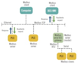
Figure 2: Modbus TCP is typically implemented on an Ethernet network, and data transactions from a client are directed toward a server via an IP address.
Modbus is an application-layer protocol, independent of the data transmission medium. Data transactions are based on the master/client requesting data from or writing data to the slave/server. The data transactions are controlled by the master/client and there is no data-by-exception transmitted in standard Modbus. Data is based on 16-bit registers that can contain discrete on/off or 16-bit integer values. Some implementations use two or more integer registers to represent floating data or long integer values. Diagnostic data can be requested by a Modbus serial master from the slave, and the slave/server can send error codes to the master/client if they perceive there is something wrong with the request they received. Modbus data transactions only contain a function code, register addresses and data, and it is up to the master/client and the slave/server to make sense of the data.
There are two types of serial Modbus, RTU and ASCII. RTU and ASCII transmission modes determine the way in which the Modbus messages are encoded. In Modbus RTU, bytes are sent consecutively with no space in between them, with a 3-1/2-character space between messages as a delimiter. This allows the Modbus interface software to know when a new message is starting. For each eight–bit byte, one start bit, eight data bits, one bit for parity, and one stop bit are sent, for a total of 11 bits per byte. Each Modbus RTU message is terminated with an error checksum called a cyclic redundancy check (CRC).
Modbus ASCII marks the start of each message with an ASCII colon character " : " and the end of each message is terminated with ASCII carriage return/line feed (CR/LF) characters. This allows the spacing between bytes in the message to be variable, which makes it suitable for transmission through some modems.The data in a Modbus ASCII message uses ASCII characters. For each eight–bit byte, one start bit, seven data bits, one bit for parity, and one stop bit are sent, for a total of 10 bits. Modbus ASCII messages are terminated with an error checksum called a longitudinal redundancy check (LRC).
The trade-off between the two types is that Modbus ASCII is easier to read if you look at the message, but the RTU messages are smaller-sized, which allows for more data exchange in an identical time period. All devices on a Modbus serial link must be of the same type, either RTU or ASCII. Modbus RTU is by far the more common.
Modbus TCP or TCP/IP is basically Modbus RTU wrapped in an Ethernet (IEEE 802.3) package with the destination address as an IP address using the TCP/IP transaction protocol. The TCP port 502 is reserved for Modbus, while the new Modbus/TCP Security uses Port 802. For more information, see “MODBUS Messaging on TCP/IP Implementation Guide” V1.0b at Modbus.org.
Addressing and messaging
Modbus memory addressing is generally organized around 16-bit registers that contain 16 coils or on/off (0/1) states or integer values in 16-bit registers (input/output or holding registers). While some devices will use their own Modbus addressing, typical Modbus addressing can be seen in Figure 3.
Modbus messaging is based on what is called an application data unit (ADU) and a Protocol Data Unit (PDU). The Modbus message includes the slave/server address for the slave/server involved, a function code, data start addresses, and the data being sent to (written) or to be send back (read) to the master/client, with an error checksum at the end (CRC/LRC/Checksum).
The size of the serial Modbus PDU is limited by the size constraint that was inherited from the first Modbus serial network implementation of 256 bytes. Modbus slave addresses are limited to 1-255. Addresses 1-247 are available to the user and addresses 248-255 are reserved.
A typical Modbus serial data transaction is shown in Figure 3. The Modbus TCP data transactions are essentially the same except the server address is an IP address, there is some Ethernet overhead, and the error checksum is different. Modbus data can include starting data addresses, data quantity or count, and actual data that is read or is to be written. If the Modbus slave/server has a problem with the master/client request, the slave/server will issue an error response back to the master/client.
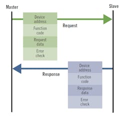
Figure 3: The Modbus TCP data transactions are essentially the same except the server address is an IP address, there is some Ethernet overhead, and the error checksum is different.
In the Modbus TCP/IP message format, the Modbus PDU is typically wrapped into the Ethernet package and consists of the Modbus function code and the Modbus data request. The slave address and error code (CRC) are typically not needed as the Modbus TCP/IP packet is routed by the network to the desired IP address (unless there is to be a connection into a serial network), and the error check is done as part of the Ethernet packet. See the “Modbus Messaging on TCP/IP Implementation Guide, V1.0b” on Modbus.org for further details.
Modbus data transactions are function code-based, which tells the Modbus slave/server what type data transaction is taking place. Function codes can be divided into public codes, user codes and reserved codes. Public function codes are well-defined and guaranteed to be unique and validated by the Modbus.org community. User function codes can be implemented and are not supported by the Modbus specification. There is no assurance that the user function code will be unique. Reserved function codes are function codes currently used by some companies for legacy products, and are not available for public use. Refer to the “Modbus Application Protocol Specification V1.1b3” at Modbus.org for more information on function codes.
Serial wiring and speed
Modbus serial traditionally uses RS-232 and RS-485 wiring for collecting data from Modbus slaves. The original Modbus was RS-232-based, but the need to connect multiple slaves soon expanded Modbus to use multidrop wiring methods. RS-422 has been used but RS-485 is more capable and is more commonly used. A Modbus master can communicate with as many as 247 Modbus slaves (limited by the RS-422/485 driver capability), which can be PLCs, smart devices, DCS and remote telemetry units (RTUs), which is where Modbus RTU got its name. “MODBUS over Serial Line Specification and Implementation Guide” at Modbus.org provides more information on wiring Modbus serial links.
To connect more than two devices and distances greater than 50 feet, a network of multidrop devices, RS-485 or RS-422 should be used. For multidrop networks, RS-485 is by far most popular and supports as many as 32 nodes without repeaters over the range as far as 4,000 ft (1,200 m).
The speed that Modbus messages are sent is known as the baud rate (or bits per second) and all devices on the network must use the same baud rate, typically 9,600-19,200 Baud, but network speeds as fast as 115 kb/s are not unknown. Generally, the higher transmission speed, the shorter the cable and the more important to have the correct network end termination resistors to minimize reflections (equal to resistance component of the cable characteristic impedance).
Safety and cybersecurity
In control systems such as a DCS, any incorrect data can potentially lead to a safety incident, whether or not a safety instrumented system (SIS) is involved. So, we must be concerned with data integrity of the Modbus data transactions—the correct data, error-free, getting to and from where it’s supposed to go. Standard Modbus has error-detection capabilities such as parity, CRC/LRC and checksums as well as diagnostics from the slave/server or master/client interfaces. These protections should be adequate for normal data transactions, but not against cybersecurity attacks or internal security breaches.
Modbus is commonly used to read data and status from SIS for the SIS HMI as required by the SIS standard IEC 61511, which is typically on the basic process control system (BPCS), commonly a DCS. Writing to the SIS via Modbus is less common and should be done cautiously. Failure of the Modbus communication link between the BPCS and the SIS should not compromise the safety integrity of the safety functions in the SIS. This also means that there must be provisions to protect against writing bad data from the BPCS or from other sources into the SIS. This same logic should apply to any independent protection layer (IPL) that uses Modbus.
Modbus was designed to read and write data and not for safety-critical functionality. The use of Modbus for safety-critical actions should be risk-assessed, and if it’s used, protections should be put in place to ensure the safety integrity of the Modbus data that performs a safety-critical function. Use of communication links like Modbus in SIS is covered by IEC 61511-1. Essentially, failure of the Modbus link cannot be able to affect the SIS safety integrity. Potential failures include failures caused by a security breach that affect the Modbus data and the SIS safety integrity. ISA technical reports on fieldbus (TR84.00.07) and cybersecurity (TR84.00.09) provide additional guidance.
If the control system and networks comply to IEC 62443, the exposure of the Modbus networks to cybersecurity attacks is reduced. Using the new Modbus/ TCP Security protocol can further reduce the cybersecurity exposures of your Modbus TCP data transactions—see “Modbus/TCP Security Protocol Specification, 2018” on Modbus.org.
By its hardwired nature, Modbus serial has less cybersecurity exposure than Ethernet-based client/server communications using Modbus TCP, especially when the Ethernet is connected to a larger process control network, which can be connected to the corporate enterprise network and/or to the Internet. Modbus serial can be exposed to a cybersecurity attack on the control system side of the master or if it is connected to a Modbus TCP network. Using Ethernet-based Modbus TCP without additional protection can greatly increase the odds that a security breach may be possible.
The Modbus TCP network’s cybersecurity exposure can be further reduced by using security appliances or firewalls specifically designed for Modbus with deep packet inspection, such as those available from Tofino Security. A security appliance/Modbus firewall should always be placed between a Modbus TCP network and a Modbus serial network, and between any remote access into a Modbus Ethernet network. (Here, the term “Modbus firewall” means a firewall or security appliance specifically designed for Modbus data transactions that has deep packet inspection, whitelisting and other security features related to Modbus.) Figure 4 shows a simple network example for Modbus TCP/Serial with SIS systems and broken down into zones and conduits per IEC 62443. There are many different possible network configurations, and only the Modbus portion of the zones and conduits are shown in this example.
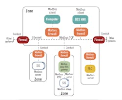
Figure 4: This simple network example for Modbus TCP/serial with SIS systems is broken down into zones and conduits per IEC 62443. There are many different possible configurations, and only the Modbus portion of the zones and conduits are shown.
Modbus troubleshooting
Troubleshooting Modbus can be broken into two general pieces, Modbus TCP/IP and Modbus Serial. Troubleshooting Modbus TCP/IP can be broken down into network troubleshooting, such as making sure that the Modbus TCP/IP Ethernet packets with error-free data get to and from where they are supposed to go to perform the desired transactions. Troubleshooting Ethernet is typically an IT function, but may be done by other personnel if an industrial Ethernet is used. Once inside the target device, troubleshooting the data transaction is typically the same as in a Modbus serial device and the troubleshooting is similar.
The first question to ask when troubleshooting a Modbus link whether the problem is new—did the Modbus link work in the past, or it has never worked? If it worked before for a Modbus TCP link, this means that the Ethernet and device configurations are probably OK.
The same applies to a Modbus serial link—the Modbus type, RTU/ASCII, baud rate, start characters, parity, end characters, timing between messages, termination resistors in place, etc. are probably correct. This allows the troubleshooter to concentrate on what has changed on the link, such as new device(s), modified or changed wiring, new wiring near the existing wiring, etc. If the installation is a new one, the wiring and the Modbus configuration for all the Modbus devices on the link should be double-checked, and made sure it lines up with the Modbus link manual and documentation. A common problem for Modbus serial is to have the signal wires reversed.
The most common indications of Modbus problems are an I/O timeout (a message request was sent and a reply was not received before the interface timed out) or an error code was received from the slave/server device. This would commonly show up as a bad process variable PV or an indication of an I/O timeout on the DCS or HMI. Most Modbus devices have communication lights that blink when the device is communicating and some will use colored LED to provide some troubleshooting capability.
When a Modbus slave/server has detected a problem with a request, it will respond to the master/client with an exception code. The meanings of the exception codes can be found in “MODBUS Application Protocol Specification V1.1b3” on Modbus.org. It may not be possible to determine what Modbus exception code is causing the problem from the DCS and you may have to look at the actual Modbus transaction. There are free and paid software packages available that will allow you see and generate Modbus messages for testing purposes. Once you get past the wiring and configuration problems, it’s almost always necessary to look at the actual Modbus data transaction to see what the problem is.
If you are placing a different manufacturer’s hardware on a Modbus Link and having a problem, it probably revolves around the Modbus master interface software, and reading the device manual is a must. If you are apparently reading or writing data but not to the right memory locations, the interface memory addressing may not agree with the slave addressing, or data types don’t agree. You may also be having problems with a memory offset—the original addressing in the Modbus message started at zero, while the memory location used in the PLC was started at one, e.g. coil 1 has a message memory location of 0 and holding register address of zero in the Modbus message has a memory location of 40001. This offset is retained in many of the modern Modbus interfaces and devices. Also, Modbus uses big-endian data flow for addresses and data (the most significant data byte sent first, lower significant byte second) but some Modbus interfaces for vendor-specific equipment may use little-endian addresses (least significant data byte sent first, most significant byte second). Using the programs that allow you to see and send messages to a slave can allow you see addressing, function codes, data sent, and what error codes are being returned from what slave/server. Modbus 07 and 08 function codes and sub-codes can be used to get additional diagnostic information on serial links (see “MODBUS over Serial Line Specification and Implementation Guide, V1.02,” on Modbus.org).
If you are experiencing noise or intermittent or strange problems with a Modbus serial link, the problem is likely related to grounding, incorrect shielding, or wiring power wires next to Modbus wiring. RS-485 two-wire and four-wire require a common line that is grounded at one point only, in addition to the two or four wires.
In summary, the use of Modbus in process control systems and factory automation is common primarily due to its simplicity and its availability. Modbus serial is based on a master/slave architecture, while Modbus TCP is client/server-based. Modbus' primary functionality is to read or write data between the master/client and slaves/servers. Modbus data is based on 16-bit registers and it is up to the Modbus master/server or slave/client to understand what the data is and what it relates to.
Modbus does not have any inherent protections against inadvertent or malicious assaults on its data transactions from cybersecurity attacks, and requires additional protections. The use of Modbus for safety-critical actions should be risk-assessed, and if used in safety-critical applications, protections should be put in place to ensure the safety integrity of the Modbus data that performs a safety-critical function.
About the author:
Frequent contributor William (Bill) L. Mostia, Jr., P.E., principle engineer, WLM Engineering Co., can be reached at [email protected].
